


Understanding UPS Operation
7-14
EATON Powerware
®
9390 UPS (100–160 kVA) Installation and Operation Manual S 164201604 Rev B powerware.com
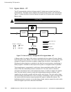
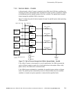
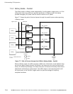
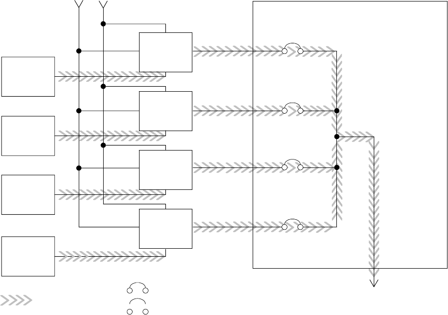
7.3.4 Battery Mode – Parallel
The UPMs transfer to Battery mode automatically if a utility power outage occurs, or if the
utility power does not conform to specified parameters. In Battery mode, the battery
provides emergency DC power that the inverter converts to AC power.
Figure 7-7 shows the path of electrical power through the parallel system when operating
in Battery mode.
Main Power Flow
UPM 1
UPM 2
UPM 3
UPM 4
Output to
Critical
Load
Battery
UPM Input
Module Tie Cabinet
UPM 1 Output
Bypass Input
UPM 2 Output
UPM 3 Output
UPM 4 Output
Battery
Battery
Battery
Closed
Open
Breakers
Figure 7-7. Path of Current through the UPMs in Battery Mode – Parallel
While in Battery mode, the UPMs sound an audible horn, illuminate a visual indicator lamp
on the front panel (System Normal, On Battery), and create an entry into the alarm event
history. As the battery discharges, the boost converter and inverter constantly make minute
adjustments maintaining a steady output. The UPMs remain in this operating mode until
the input power to the rectifier is again within the specified voltage or frequency
acceptance windows.