


Understanding UPS Operation
7-8
EATON Powerware
®
9390 UPS (100–160 kVA) Installation and Operation Manual S 164201604 Rev B powerware.com
7.2.4 Battery Mode – RT
The UPS automatically transfers to Battery mode if a utility power outage occurs, or if the
utility power does not conform to specified parameters. In Battery mode, the battery
provides emergency DC power that the inverter converts to AC power.
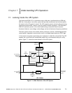
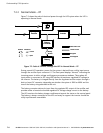
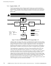
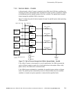
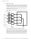
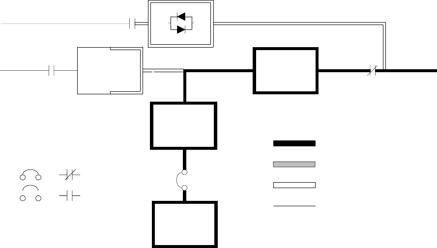
Figure 7-4 shows the path of electrical power through the UPS system when operating in
Battery mode.
Static
Switch
K5
Rectifier Inverter
K1 K3
Battery
Converter
Battery
CB2
Main Power Flow
Trickle Current
Energized
De-Energized
Closed
Open
Breakers Contactors
Figure 7-4. Path of Current Through the UPS in Battery Mode – RT
During a utility po wer failure, the rectifier no longer has an AC utility source from which to
supply the DC output current required to support the inverter. The input contactor K1
opens and the battery instantaneously supplies energy to the battery converter. The
converter either bucks or boosts the voltage so that the inverter can support the
customer’s load without interruption. If bypass is common with the rectifier input, the
backfeed protection contactor K5 also opens. The opening of contactors K1 and K5
prevent system voltages from bleeding backwards through the static switch and rectifier
snubber components and re-entering the input source.
While in Battery mode, the UPS sounds an audible horn, illuminates a visual indicator lamp
on the front panel (System Normal, On Battery), and creates an entry into the alarm event
history. As the battery discharges, the converter and inverter constantly make minute
adjustments to maintain a steady output. The UPS remains in this operating mode until the
input power to the rectifier is again within the specified voltage or frequency acceptance
windows.