


vii
EATON Powerware
®
9390 UPS (100–160 kVA) Installation and Operation Manual S 164201604 Rev B powerware.com
Table of Contents
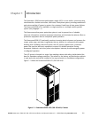
Figure 1-1. Powerware 9390 UPS (100–160 kVA) Cabinet 1-1...................................
Figure 2-1. Powerware 9390 UPS (100–160 kVA) Cabinet as Shipped on Pallet 2-3.................
Figure 3-1. Removing Front Shipping Bracket on the Powerware 9390 UPS 3 -3....................
Figure 3-2. Removing Rear Shipping Bracket on the Powerware 9390 UPS 3 -4....................
Figure 5-1. REPO Switch 5-1...............................................................
Figure 6-1. Powerware Hot Sync CAN Bridge Card 6 -1........................................
Figure 6 -2. Supervisory Contact Module II TB2 6-7...........................................
Figure 7-1. Main Elements of the UPS System 7-1............................................
Figure 7 -2. Path of Current Through the UPS in Normal Mode – RT 7 -4..........................
Figure 7 -3. Path of Current Through the UPS in Bypass Mode – RT 7 -6..........................
Figure 7-4. Path of Current Through the UPS in Battery Mode – RT 7 -8..........................
Figure 7 -5. Path of Current through the UPMs in Normal Mode – Parallel 7 -11.....................
Figure 7 -6. Path of Current through the UPMs in Bypass Mode – Parallel 7 -12.....................
Figure 7 -7. Path of Current through the UPMs in Battery Mode – Parallel 7 -14.....................
Figure 9-1. UPS Control Panel 9-1..........................................................
Figure 9 -2. Parts of the LCD 9 -2...........................................................
Figure 9-3. Main Menu and Mimic Screen (Normal Mode) 9 -3..................................
Figure 9 -4. Active Events Screen 9 -4........................................................
Figure 9-5. History Screen 9-5.............................................................
Figure 9-6. Unit Output Meter Screen 9 -6...................................................
Figure 9-7. Unit Input Meter Screen 9-7....................................................
Figure 9-8. Unit Bypass Meter Screen 9-7...................................................
Figure 9-9. Unit Battery Meter Screen 9-8...................................................
Figure 9-10. Unit Output Current (Load) Meter Screen 9 -8....................................
Figure 9 -11. Battery Discharge Log Summary Screen 9 -9.......................................
Figure 9 -12. Battery Discharge Log Screen 9-10...............................................
Figure 9-13. KW Demand Log Summary Screen 9-11...........................................
Figure 9-14. KW Demand Log Screen 9 -12...................................................
Figure 9-15. Current KW Demand Log Setup Screen 1 9 -13.....................................
Figure 9-16. Current KW Demand Log Setup Screen 2 9 -14.....................................
Figure 9 -17. Time Interval Monitored Setup Screen 9 -15.......................................
Figure 9 -18. Time Interval Monitored Setup Save Screen 9 -16...................................
Figure 9-19. Maximum Level (KW) Setup Screen 9 -17..........................................
Figure 9-20. Maximum Level (KW) Setup Save Screen 9-18......................................
Figure 9-21. Maximum Current Log Summary Screen 9 -19......................................
Figure 9-22. Maximum Current Log Screen (Three-Phase Measurement) 9 -20......................
Figure 9-23. Maximum Current Log Screen (Individual Phase Measurement) 9 -21..................