


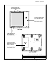
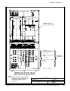
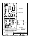
POWER WIRING INSTALLATION NOTES
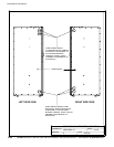
091505A
164201604---5
DESCRIPTION:
DATE:
DRAWING NO: SHEET:
REVISION:
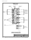
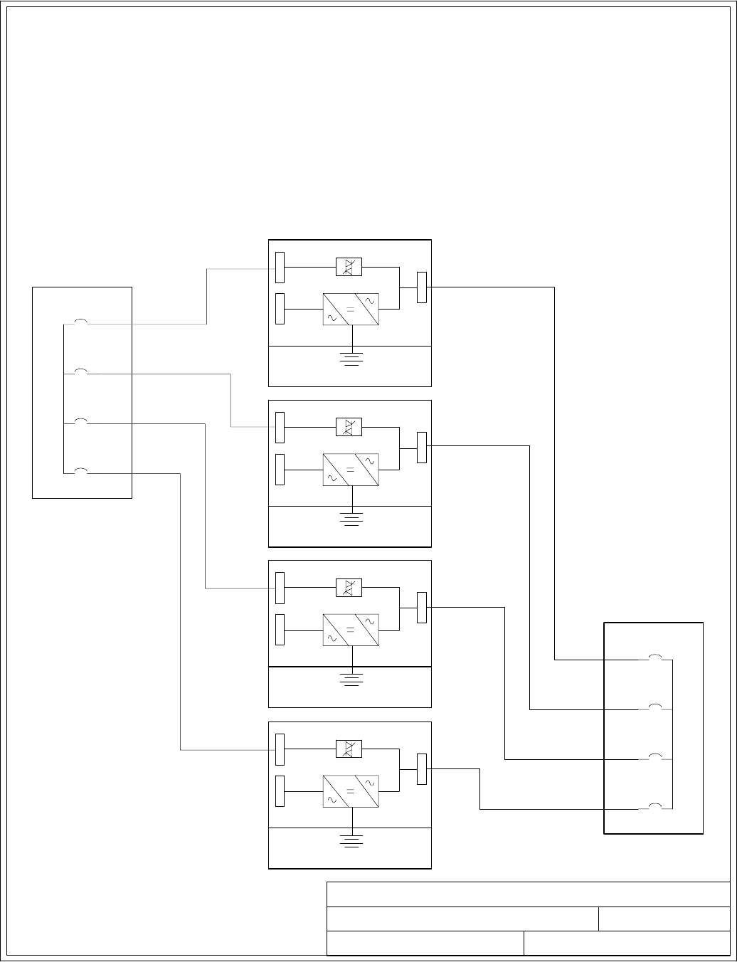
UPM2
Battery
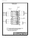
BypassinputstoUPMs
UPM1
Battery
UPM3
Battery
UPM4
Battery
OutputsfromUPMs
1A(30)
2A(35)
3A(40)
4A(45)
1B (25)
2B (20)
3B (15)
4B (10)
15 of 15
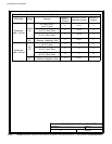
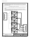
NOTE: Wire lengths in the diagram and
formula are in feet and are for
example only.
Installation Information
A-26
EATON Powerware
®
9390 UPS (100–160 kVA) Installation and Operation Manual S 164201604 Rev B powerware.com
32. Required parallel system wiring length must be in a ccordance with the following formula,
as referenced to the diagram below, to ensure approximately equal current sharing when
in Static Bypass mode:
(Total length of 1A + 1B) ≅ (Total length of 2A + 2B) ≅ (Total length of 3A + 3B) ≅ (Total length of 4A + 4B)
(30 + 25) ≅ (35 + 20) ≅ (40 + 15) ≅ (45 + 10)
This rule has a tolerance of approximately ±10% for the combined input and output wire
lengths.
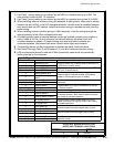
If installing only two UPMs in a fully redundant system, this requirement is no longer
required, as each UPM is capable of supporting the full bypass requirement. However, this
would preclude future expansion.