


Installing the UPS System
3-6
EATON Powerware
®
9390 UPS (100–160 kVA) Installation and Operation Manual S 164201604 Rev B powerware.com
3.2.3 Integrated Distribution Cabinet Installation
To install and wire an IDC, refer to the Powerware 9390 Integrated Distribution Cabinet
(160 kVA) Installation and Operation Manual. A fter the IDC is installed and wired, return to
paragraph 3.2.6 to complete the UPS cabinet wiring.
3.2.4 Integrated Accessory Cabinet Installation
To install and wire an IAC, refer to the Powerware 9390 Integrated Accessory Cabinet (IAC-B
and IAC-T Configurations) Installation and Operation Manual or the Powerware 9390
Integrated Accessory Cabinet (IAC -D Configuration) Installation and Operation Manual.
After the IAC is installed and wired, return to paragraph 3.2.6 to complete the UPS cabinet
wiring.
3.2.5 UPS Sidecar Wiring
To wire an UPS Sidecar, refer to the Powerware 9390 UPS Sidecar Installation and
Operation Manual. After the UPS Sidecar is wired, return to paragraph 3.2.6 to complete
the UPS cabinet wiring.
3.2.6 Installing UPS External and Battery Power Wiring
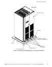
NOTE The UPS cabinet is shipped with a debris shield covering the ventilation grill on
top of the unit. Do not remove the debris shield until installation is complete. However,
remove the shield before operating the UPS. Once the debris shield is removed, do not
place objects on the ventilation grill.
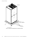
NOTE Remove the UPS cabinet top or bottom conduit landing plate to drill or punch
conduit holes (see Drawing 164201604-6 on page A -27).
NOTE Iftheloadrequiresaneutral,abypasssourceneutralmustbeprovided.Ifthe
load does not require a neutral and there is no neutral conductor connected at the
bypass input, a neutral to ground bonding jumper must be installed. DO NOT install
both a source neutral and a bonding jumper. See Table E through Table G or Table O
through Table Q for neutral bonding jumper wire sizes. Bonding jumper must be
copper wire.
CAUTION
HIGH IMPEDANCE GROUND S OURCES - If the supply source is a high impedance ground (IT)
type, the input neutral conductor must be connected from the source of supply. If there is no
output neutral connected to the UPS, the neutral-forming transformer kit (PN 103005400) may
be used instead of pulling a neutral from the source. If the load requires a neutral, then an
input neutral conductor must be pulled into the UPS. In no circumstances shall a neutral to
ground bonding jumper be installed in the UPS.