


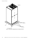


Installing the UPS System
3-8
EATON Powerware
®
9390 UPS (100–160 kVA) Installation and Operation Manual S 164201604 Rev B powerware.com
CAUTION
In the following step, DO NOT move the sensing and EMI wires from the rectifier contactor K1
input terminals. These wires must remain connected to the K1 terminals for proper UPS
operation.
10. Disconnect the phase A, B, and C bypass contactor K5 power input leads only (two
wires per phase) from the rectifier contactor K1 input terminals. Connect these
power leads to the b ypass input terminals.
11. Connect phase A, B, and C rectifier input power wiring from the utility source to
the rectifier input terminals in the UPS cabinet. See Appendix A for wiring and
termination requirements and wiring access information. Note wiring connections
for dual-feed systems.
12. Connect phase A, B, and C, and Neutral (if required) bypass input power wiring
from the utility source to the bypass input terminals and neutral terminals in the
UPS cabinet. See Appendix A for wiring and termination requirements and wiring
access information. Note wiring connections for dual-feed systems.
13. If wiring an IDC or IAC, proceed to Step 14; otherwise, proceed to Step 17.
14. Route and connect the output cable between the UPS cabinet and the IDC or IAC.
Refer to the applicable IDC or IAC installation and operation manual, referenced in
paragraph 1.5 on page 1-6, for wiring instructions. See Appendix A for UPS cabinet
wiring access information.
15. Connect phase A, B, and C, and Neutral (if required) power wiring from the IDC or
IAC to the UPS cabinet output and neutral terminals. See Appendix A for wiring
and termination requirements.
16. Proceed to paragraph 3.2.6.3.
17. If wiring a parallel system, proceed to Step 18; otherwise, proceed to Step 20.
CAUTION
Parallel system wiring length should be in accordance with Drawing 164201604-5, sheet
15 of 15, to ensure approximately equal current sharing when in Static Bypass mode.
18. Connect phase A, B, and C, and Neutral (if required) power wiring from the output
and neutral terminals of each uninterruptible power module (UPM) to the module
tie cabinet. See Appendix A for UPM wiring and termination requirements and
wiring access information.
19. Proceed to paragraph 3.2.6.3.
20. Connect phase A, B, and C, and Neutral (if required) power wiring from the output
and neutral terminals to the critical load. See Appendix A for wiring and
termination requirements and wiring access information.
21. Proceed to paragraph 3.2.6.3.