


Understanding UPS Operation
7-9
EATON Powerware
®
9390 UPS (100–160 kVA) Installation and Operation Manual S 164201604 Rev B powerware.com
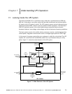
If the input power fails to return or is not within the acceptance windows required for
normal operation, the battery continues discharging until a DC voltage level is reached
where the inverter output can no longer support the connected loads. When this event
occurs, the UPS issues another set of audible and visual alarms indicating SHUTDOWN
IMMINENT. Unless the rectifier has a valid AC input soon, the output can b e supported for
only two minutes before the output of the system shuts down. If the bypass source is
available, the UPS transfers to bypass instead of shutting down.
If at any time during the battery discharge the input power becomes available again,
contactors K1 and K5 close and the rectifier begins to supply DC current to the converter
and inverter. At this point, the unit returns to Normal mode. Depending on the total load
and the duration of the battery discharge, battery current limit alarms may be seen for a
short time due to the current required to recharge the battery.
The system’s total operating time on battery depends on many factors. Some factors that
affect battery support times are battery type and capacity, number of parallel strings,
environmental temperatures, age of the battery, and fluctuations in load demand during
the discharge. The greater the load, the less support time the battery has. Decreasing the
load generally increases the battery support time.
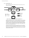
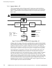
7.3 Multiple Module Parallel System
Parallel operation extends the normal operation of Powerware 9390 UPS units by offering
increased capacity and/or redundant capability. The parallel system continues to maintain
power to the critical loads during commercial electrical power brownout, blackout,
overvoltage, undervoltage, and out-of-tolerance frequency conditions. See Drawing
164201604-4, sheets 4 of 6, 5 of 6, and 6 of 6 in Appendix A, for a detailed relationship of
the parallel system.
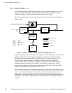
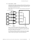
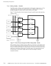
The output of the system is normally supplied by several uninterruptible power modules.
Multiple UPMs are connected with their outputs in parallel (tied together) to provide a
load level greater than the rating of one UPM and/or for redundancy. The paralleled UPMs
supply the output load with protected power as long as the load does not exceed the
combined rating of the paralleled UPMs.
The power system is redundant as long as one of the UPMs c an be disconnected from the
output bus and the remaining UPMs can continue to supply power to the load without
exceeding their ratings.
When the load is being supplied by the UPMs, the system output bus is continuously
monitored for an overvoltage or undervoltage condition. If an out of limits condition is
detected, the paralleled UPMs transfer the load to bypass using the UPM static switches.
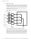
Communication is required between the UPMs for system metering and mode control.
System level communication and control are accomplished using a Computer Area
Network. A single building alarm in each UPM, connected to the other UPMs in parallel,
and tied to the bypass contactor auxiliary contacts in each UPM are used for a secondary
communication path. This arrangement ensures bypass control even if the CAN bus is lost.