


POWER WIRING INSTALLATION NOTES
091505A
164201604---5
9of15
DESCRIPTION:
DATE:
DRAWING NO: SHEET:
REVISION:
Installation Information
A-20
EATON Powerware
®
9390 UPS (100–160 kVA) Installation and Operation Manual S 164201604 Rev B powerware.com
19. There is no DC disconnect device within the U PS.
20. A battery disconnect switch is recommended, and may be required by NEC or local codes
when batteries are remotely located. The battery disconnect switch should be installed
between the battery and the UPS.
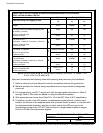
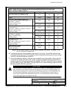
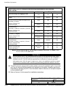
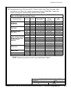
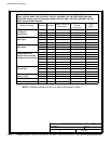
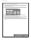
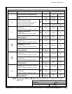
21. External DC input overcurrent protection and disconnect switch for the remote battery
location is to be provided by the user. Table M lists the maximum rating for continuous-duty
rated circuit breakers satisfying the criteria for both.
Table M. Maximum DC Input Circuit Breaker Ratings
UPS Model
Input Voltage Rating
208V/220V 480V
Powerware 9390---120/100
Powerware 9390---160/100
400A 400A
Powerware 9390---120/120
Powerware 9390---160/120
450A 450A
Powerware 9390---160/160 600A 600A
22. Battery voltage is computed at 2 volts per cell as defined by Article 480 of the NEC.
Rated battery current is computed at 2 volts per cell.
23. The battery wiring used between the battery and the UPS should not allow a voltage drop
of more than 1% of nominal DC voltage at rated battery current.
24. If the conductors used for DC input from the battery cabinets to the UPS are those
provided by the UPS manufactu rer, and the UPS and battery cabinets are m anufactured by
the same supplier, t hen it is acceptable if they do not meet the noted minimum conductor
sizes.