Chapter 5 Configuring a Typical Application Installation and Operation Manual
5-4 Configuring the ASMi-52 units ASMi-52 Ver. 2.5
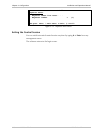
2. From the Framed Mode menu, select Unframed to choose the unframed
operation.
The E1 Local Port menu appears.
3. Save the changes.
After performing these configuration procedures, the ASMi-52 units are ready to
be connected.
Configuring the Line Interface Type
You can configure the ASMi-52 units with 4-wire interface to operate over 2-wire
lines. Selecting the 2-wire operation mode disables pin 1 and pin 2 of the RJ-45
line connector.
To configure the line interface type for ASMi-52 units:
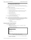
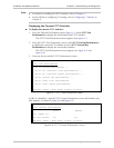
1. From the SHDSL Local Port Configuration menu, select Configured Wire
The display is refreshed and a new value appears (2W or 4W).
2. Select Save to save the changes
3. Reset ASMi-52 in order to active the change.
Configuring the Serial DTE Interface
If the ASMi-52 modem is equipped with a serial data interface, the configuration
software allows you to enable/disable the LLB/RLB activation from the DTE (except
for X.21) and select the modem’s data rate.
Configuring LLB/RLB Activation from DTE
To enable/disable the LLB/RLB activation from DTE:
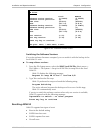
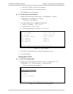
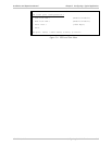
1. From the DTE Configuration menu, select DTE Local Port Configuration
(Main menu > Configuration > DTE Configuration > DTE Local Port) to
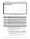
configure the DTE local port (see Figure 5-5).
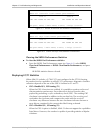
The DTE Local Port menu appears (see Figure 5-6).
2. From the DTE Local Port menu, select LLB from DTE to enable the LLB
activation from the DTE or select RLB from DTE to enable the RLB activation
from the DTE.
The display is refreshed and a new value appears.
3. Select Save to save the changes.
ASMi-52
DTE configuration >
Port number (1)
1. DTE local port
2. DTE remote port
>
ESC-prev. menu; !-main menu; &-exit; @-scroll
Figure 5-5. DTE Configuration Menu


