Installation and Operation Manual Chapter 1 Introduction
ASMi-52 Ver. 2.5 Functional Description 1-11
Modem Glue
Logic
Data & Clock
LEDs and Terminal Interface
Control Signals
CPU
10/100BaseT
Management
Port
CPU Data Bus
DTE
Interface
SHDSL
Line Interface
Power
Supply
Internal
Oscillator
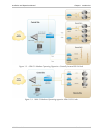
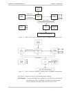
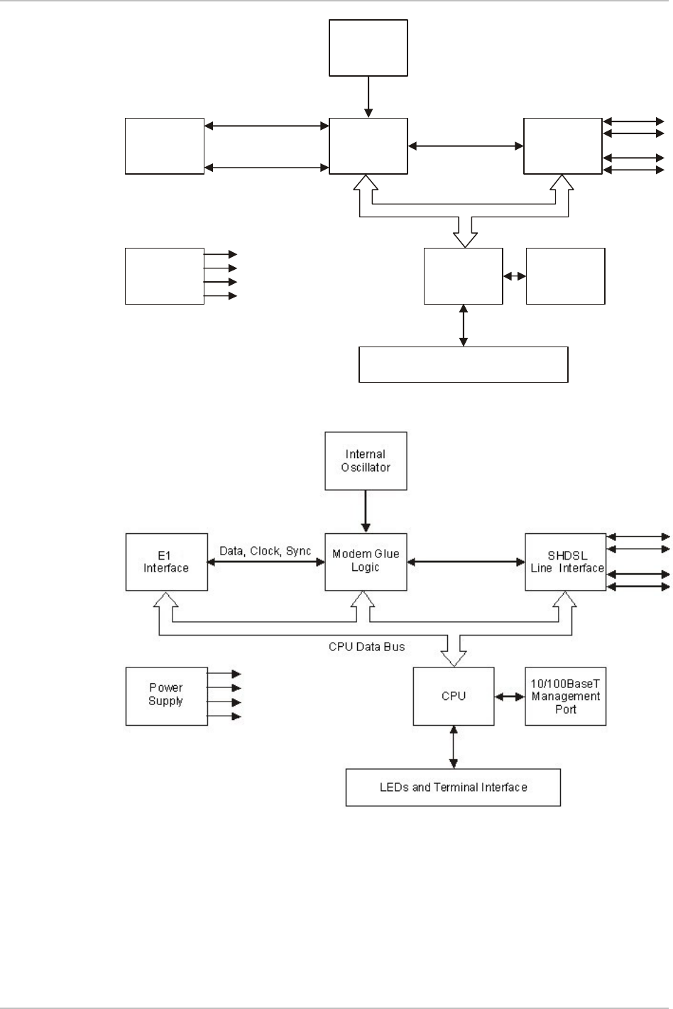
Figure 1-5. ASMi-52/4W with V.35 Interface and 10/100BaseT Management Port
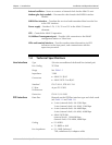
Figure 1-6. ASMi-52/4W with Framed E1 Interface and 10/100BaseT Management
Port
The ASMi-52 modem consists of the following major modules:
DTE interface – Prepares the digital data coming from the DTE into a data stream
for modem glue logic. In addition, it translates the data from the
modem glue logic into digital data to be sent to the DTE.


