


Installation and Operation Manual Appendix A Interface Connector Specifications
ASMi-52 Ver. 2.5 Alarm Relay Connector A-5
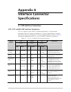
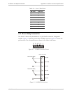
Table A-6. Cross Cable Pinout
DB-9 Pin DB-9 Pin
2 3
3 2
4 6
5 5
6 4
7 8
8 7
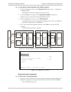
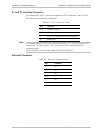
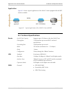
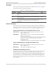
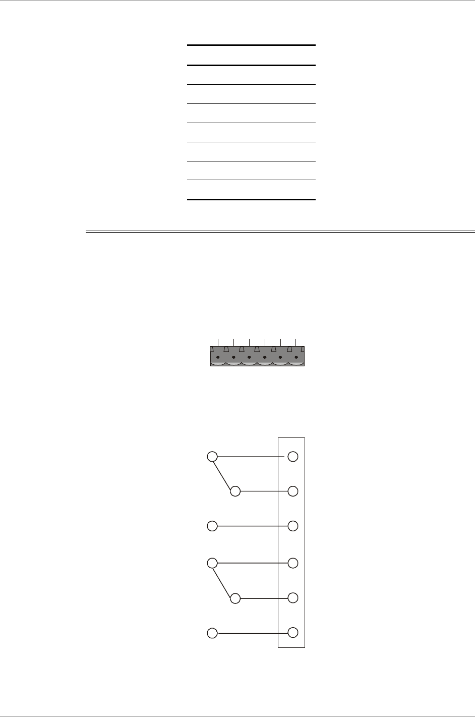
A.3 Alarm Relay Connector
The ASMi-52 alarm relay terminates in a 6-pin female connector, designated
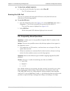
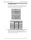
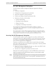
ALARM. Figure A-1 lists the pinout of the ALARM connector. Figure A-2 shows the
pin functions. The relay positions are shown in the Alarm Active state.
123456
Figure A-1. ALARM Connector Pinout
Alarm Connector
Minor-NO
1
2
3
4
5
6
Major-NO
Major Alarm Relay
Minor Alarm Relay
Minor-NC
Major-NC
Minor-COM
Major-COM
Figure A-2. ALARM Pin Functions