


Chapter 1 Introduction Installation and Operation Manual
1-12 Technical Specifications ASMi-52 Ver. 2.5
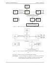
Internal oscillator – Serves as a source of internal clock for the ASMi-52 unit.
Modem glue logic module – Processes the data from/to the SHDSL interface
module.
SHDSL line interface – Translates the received and transmitted data from the line
to the DTE interface.
Power supply – Provides 2.5V, 3.3V, 5V and -5V to the ASMi-52 internal
elements.
CPU – Controls the ASMi-52 operation.
10/100BaseT management port – Provides LAN connection to the SNMP
management station or Telnet host.
LEDs and terminal interface – Provides modem status information via LED
indicators on the front panel, and communicates with the
supervisory terminal.
1.4 Technical Specifications
Line Interface
Type
2/4-wire unconditioned dedicated line (twisted pair)
Line Coding
TC-PAM
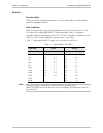
Range
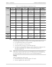
See Table 1-1
Impedance
135Ω
Connectors
• ASMi-52: RJ-45
• ASMi-52CD: Two RJ-45
Standard
ITU-T 991.2, ETSI 101 524
E1 Jitter
Performance
As per ITU G.823
Protection
ITU K.21, UL1950
DTE Interface
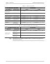
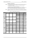
Data Rate
Depends on the DTE/line interface type and clock mode
(see Table 1-2 and Table 1-3)
• 2-wire (external clock): 64–2304 kbps,
2-wire (internal clock): 64–2048, 2304 kbps
• 4-wire (external clock): 64–4608 kbps,
4-wire (internal clock): 64–4096, 4608 kbps
• ASMi-52CD/4W:
(external clock): 128-4608 kbps
(internal clock): 128-4096, 4608 kbps
Coding
• E1: HDB3
• T1: B8ZS or AMI
Line Impedance
• E1: 120Ω, balanced
75Ω, unbalanced (via adapter cable)