


ASMi-52 Ver. 2.5 Controls and Indicators 3-1
Chapter 3
Operation
This chapter provides the following information for the ASMi-52 modem:
• ASMi-52 front-panel indicators
• Operating procedures (turn-on, front-panel indications, performance
monitoring and turn-off)
• ASMi-52 default settings.
Installation procedures given in Chapter 2 must be completed and checked before
attempting to operate ASMi-52.
3.1 Turning On ASMi-52
To turn on ASMi-52:
• Connect the power cord to the mains.
The PWR indicator lights up and remains lit as long as ASMi-52 is receiving
power.
ASMi-52 requires no operator attention once installed, with the exception of
occasional monitoring of front panel indicators. Intervention is only required when
ASMi-52 must be configured to its operational requirements, or diagnostic tests are
performed.
3.2 Controls and Indicators
The front and rear panels of ASMi-52 include a series of LED indicators that show
the current operating status of the unit.
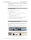
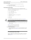
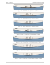
Figure 3-1 shows the front panel of the 2-wire ASMi-52 unit in a plastic enclosure
with an E1 interface. Figure 3-2, Figure 3-3, Figure 3-4, Figure 3-5, Figure 3-6, and
Figure 3-7 illustrate the front panel options for the ASMi-52 4-wire unit in its plastic
enclosure with E1/T1, IR (DTE Serial Data), and Ethernet interfaces.
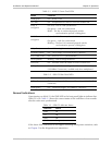
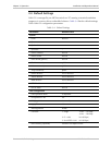
Table 3-1 lists and describes the front panel indicators. Table 3-2 lists and describes
the rear panel indicators.