


Installation and Operation Manual Chapter 3 Operation
ASMi-52 Ver. 2.5 Controls and Indicators 3-3
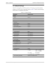
Table 3-1. ASMi-52 Front Panel LEDs
Name Function
PWR (green) On – Power is ON
TST (red) On – A loopback test is active in a local or remote unit
SYNC A
(red/green)
On (red) – Link A is not synchronized
On (green) – Link A is synchronized
Blinks – The line is connected properly and the
synchronization process is taking place
SYNC B
(red/green)
On (red) – Link B is not synchronized
On (green) – Link B is synchronized
Blinking – The line B is connected properly and the
synchronization process is taking place
AIS (yellow) On – “All 1s string” is received at the E1 interface
YELLOW (yellow) On – “All 1s string” is received at the T1 interface
E1/T1 SYNC (red) On – Loss of E1 or T1 synchronization
DATA (yellow) Blinking – Data is being transferred
ALM (red) On – An alarm enters the buffer of local or remote unit
ACT (yellow) For Ethernet, blinks according to the Ethernet traffic activity
(10/100BaseT connector), available only when multiplexed
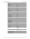
Table 3-2. ASMi-52 Rear Panel LEDs
Name Function
ACT (yellow) Blinks according to the Ethernet traffic activity (10/100BaseT
connector)
LINK (green) On – Good link integrity (10/100BaseT connector)
Normal Indications
Upon turning on ASMi-52, the PWR LED in the front panel lights to indicate that
ASMi-52 is on. Table 3-3 shows the correct status of the indicators a few seconds
after the units were synchronized.
Table 3-3. ASMi-52 Indicator Status
Indicator Status
PWR On
TST Off
ALM Off
SYNC On (green)
If the above LED indications do not appear following initial power activation, refer
to Chapter 5 for the diagnostic test instructions.