Page 244 SonicWALL Internet Security Appliance Administrator’s Guide
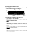
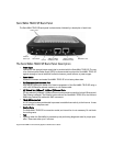
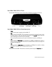
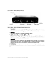
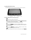
SonicWALL TELE3 SP Back Panel
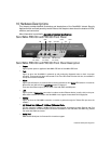
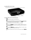
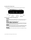
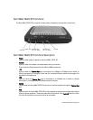
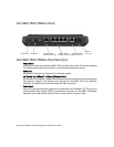
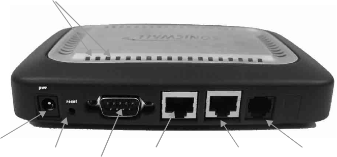
The SonicWALL TELE3 SP back panel is shown below, followed by a description of each item.
The SonicWALL TELE3 SP Back Panel Description
• Power Input
Connects to the external power supply that is provided with the SonicWALL TELE3 SP. The use
of an Uninterruptible Power Supply (UPS) is recommended to protect the SonicWALL TELE3 SP
against damage or loss of data due to electrical storms, power failures, or power surges.
• Reset Switch
Erases the firmware and resets SonicWALL TELE3 SP to its factory clean state.
• CLI (Command Line Interface) Port
DB-9 RS-232 Serial port allows out of band management of the SonicWALL TELE3 SP using a
v.90/v.92 US Robotics external modem or a null-modem cable.
• (2) Twisted Pair (10Base-T, 100Base-T) Ethernet Ports
(2) Auto switching 10Mbps/100Mbps Ethernet ports provide connectivity for both Ethernet and
Fast Ethernet networks. The Ethernet ports connect the SonicWALL TELE3 SP to the LAN and
WAN using Twisted Pair cable with RJ45 connectors.
• TELE3 SP Modem Port
A V.90 internal modem provides dial-up access to establish connectivity to the Internet. It uses
a standard RJ-11 telephone cord.
• Cooling Vents
The SonicWALL TELE3 SP is convection cooled; an internal fan is not necessary. Do not block
the cooling vents.
• Test
• Lights up when the SonicWALL is powered up and performing diagnostic tests for proper oper-
ation. These tests take up to 5 minutes.
10Mbps/100Mbps
LAN Ethernet Port
Reset Switch
CLI Port
10Mbps/100Mpbs
WAN Ethernet Port
5VDC,2A
Power input
Cooling Vents
WAN Modem Port


