Chapter 4 Hardware Installation 53
1. Working from the back, connect the power cord(s).
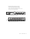
FIGURE 4-9 shows the 8-port switch power connector.
FIGURE 4-10 shows the 16-port switch power connector.
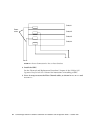
FIGURE 4-11 shows the power connections for two or four switches.
Allow the power cord to dangle temporarily.
FIGURE 4-9 The 8-Port Switch Power Connector
FIGURE 4-10 The 16-Port Switch Power Connector
Power
GBIC
Port 1
Port 8
Port 2
Port 4
Port 6
Port 3
Port 5
Port 7
microsystems
Power
Port 1 Port 3 Port 5 Port 7 Port 9 Port 11 Port 13 Port 15
Port 2
Port 4
Port 6 Port 8 Port 10 Port 12 Port 14 Port 16
GBIC


