Chapter 4 Replacing Cold-Swappable Components 4-13
Note – FB-DIMM names in ILOM messages are displayed with the full name, such
as /SYS/MB/CMP0/BR0/CH0/D0.
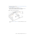
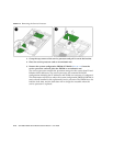
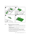
3. Note the DIMM locations so that you can install the replacement DIMMs in
the same sockets.
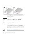
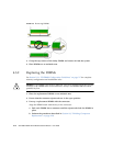
4. Push down on the ejector levers on each side of the DIMM connector until the
DIMM is released.
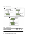
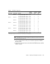
Channel 1 /SYS/MB/CMP0/BR0/CH1/D0 J1201 2 A
/SYS/MB/CMP0/BR0/CH1/D1 J1301 3 B
Branch 1 Channel 0 /SYS/MB/CMP0/BR1/CH0/D0 J1401 1 C
/SYS/MB/CMP0/BR1/CH0/D1 J1501 3 D
Channel 1 /SYS/MB/CMP0/BR1/CH1/D0 J1601 2 C
/SYS/MB/CMP0/BR1/CH1/D1 J1701 3 D
Branch 2 Channel 0 /SYS/MB/CMP0/BR2/CH0/D0 J2001 1 E
/SYS/MB/CMP0/BR2/CH0/D1 J2101 3 F
Channel 1 /SYS/MB/CMP0/BR2/CH1/D0 J2201 2 E
/SYS/MB/CMP0/BR2/CH1/D1 J2301 3 F
Branch 3 Channel 0 /SYS/MB/CMP0/BR3/CH0/D0 J2401 1 G
/SYS/MB/CMP0/BR3/CH0/D1 J2501 3 H
Channel 1 /SYS/MB/CMP0/BR3/CH1/D0 J2601 2 G
/SYS/MB/CMP0/BR3/CH1/D1 J2701 3 H
* Upgrade path: DIMMs should be added with each group populated in the order shown.
\ Fault replacement path: Each pair is addressed as a unit, and each pair must be identical.
TABLE 4-2
FB-DIMM Configuration
Branch Name Channel Name FRU Name
Motherboard
FB-DIMM
Connector
FB-DIMM
Installation
Order
*
FB-DIMM
Pair
\


