


4 Replacement Procedures 4.8 Palm rest/Touch pad
4-18 PORTEGE A100 Maintenance Manual (960-460)
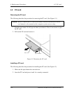
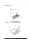
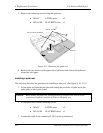
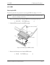
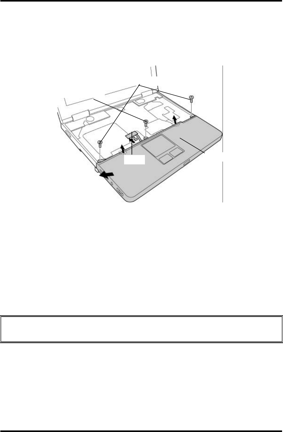
3. Remove the following screws fixing the palm rest.
• M2×3C S-THIN screw x2
• M2.5×12B FLAT BIND screw x1
PJ3201
M2
×
3C S-THIN
Palm rest
M2.5
×
12 B FLAT BIND
Figure 4-11 Removing the palm rest
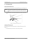
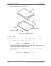
4. Remove the two latches on the upper side of palm rest and remove the palm rest
toward the left upper.
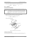
Installing a palm rest
The following describes the procedure for installing a palm rest. (See Figure 4-10, 4-11.)
1. Set the palm rest from the left side while fitting the two holes of palm rest to the
audio jacks on the system board.
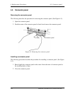
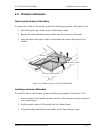
Caution: When setting the palm rest, fit the position of wireless LAN switch on the
system board and the position of slider on the palm rest.
2. Fix the palm rest with the following screws.
• M2×3C S-THIN screw x2
• M2.5×12B FLAT BIND screw x1
3. Connect the cable to the connector PJ 3201 on the system board.