


4.24 Hinge assembly 4 Replacement Procedures
PORTEGE A100 Maintenance Manual (960-460) 4-53
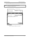
4.24 Hinge assembly
Removing the hinge assembly
To remove the hinge assembly, perform the following procedure. (See Figure 4-42, 4-43)
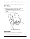
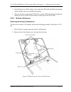
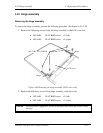
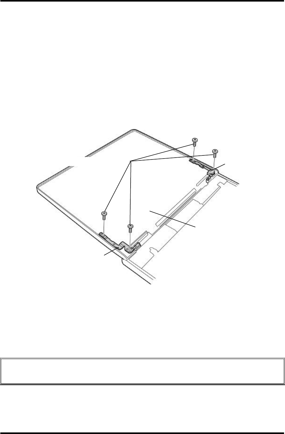
1. Remove the following screws fixing the hinge assembly on the LCD cover side.
• M2.5×4B FLAT BIND screw x2 (left)
• M2.5×4B FLAT BIND screw x2 (right)
M2.5
×
4B FLAT BIND
Hinge
Hinge
LCD cover
Figure 4-42 Removing the hinge assembly (LCD cover side)
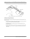
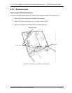
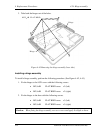
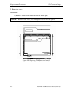
2. Remove the following screws fixing hinge assembly on the base side.
• M2.5×4B FLAT BIND screw x3 (left)
• M2.5×4B FLAT BIND screw x3 (right)
Caution: Silicon grease is applied to screws on the base side. Drive the screws a little
strongly.