


PinPoint EDGE/GPRS - User Guide, version 2.32 30
CHAPTER 6 External Inputs & Power Control
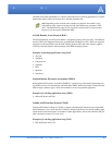
The PinPoint has special features for use in a mobile environment. The PinPoint can be configured
to monitor the inputs on its serial port and respond to specific types of events. The PinPoint can
also be configured to change its power mode in order to conserve power.
Capturing Events via External Inputs
The RS232 DB9 interface (the serial port) can be connected to digital switches and configured to
capture contact closures using RTS and DTR to signal external or physical events (such as a tow
bar being activated, opening a door or trunk, the car is turned on or off, etc.).
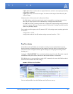
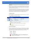
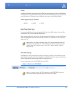
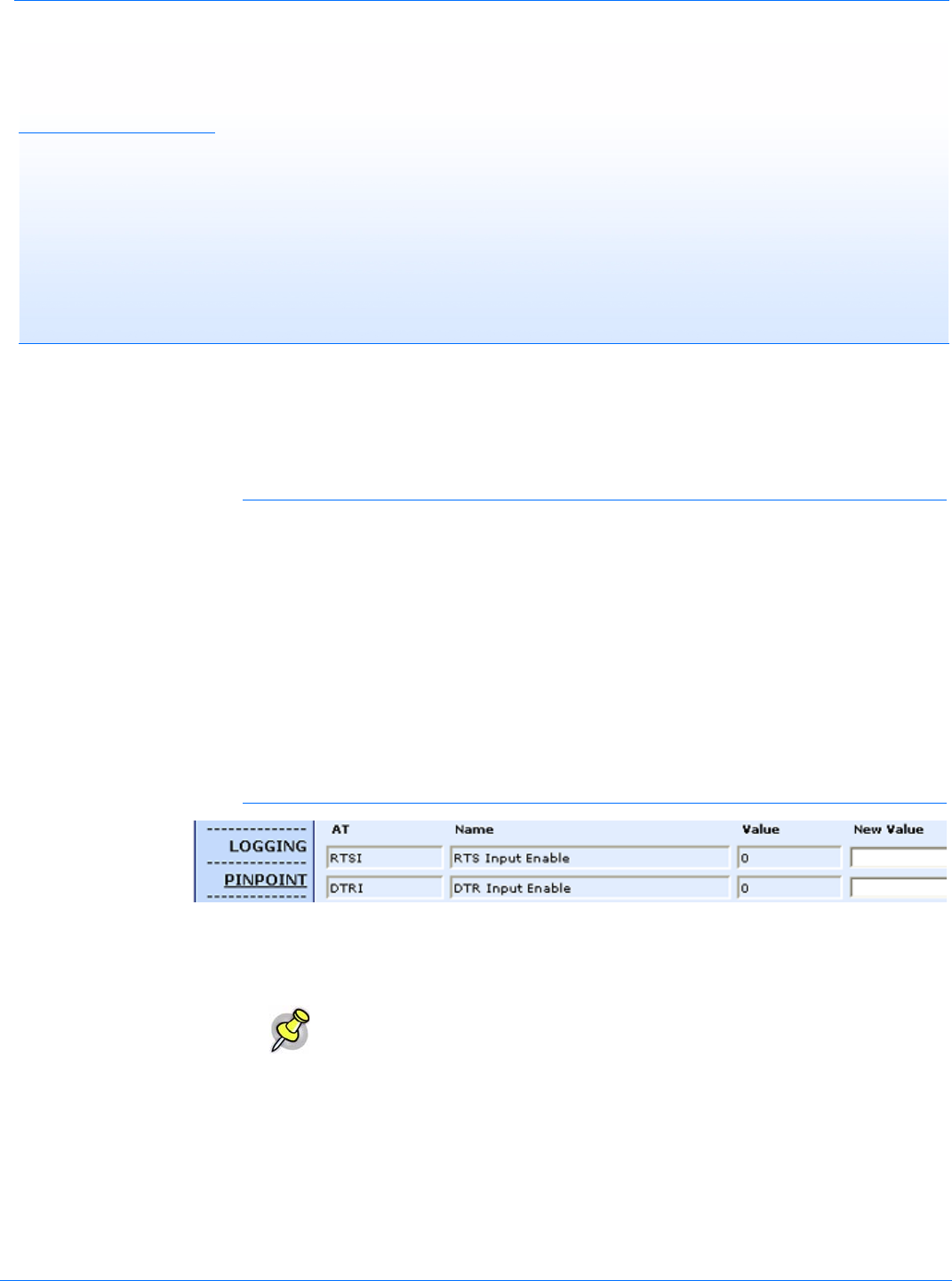
Setting the DTR and RTS
You can use either Wireless Ace, direct serial communication, or Telnet to configure the modem
using AT commands (
page 59). Select PinPoint from the menu on the left. Scroll down the com-
mand options until you see RTSI and DTRI.
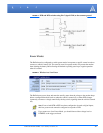
FIGURE 1. Wireless Ace: DTR and RTS
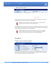
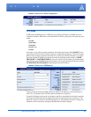
To turn on the DTR (pin 4) digital sensing in the modem, *DTRI should be set to 1. To turn on the
RTS (pin 7) digital sensing, *RTSI should be set to 1.
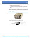
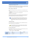
Connecting to the Serial Port
You can connect a standard RS232 serial cable to the PinPoint serial port. If you want to use the
DTR switch, wire in a Normally Open switch between the DTR (pin 4) and signal ground (pin 5),
the
PinPoint’s external case, or the power ground (refer to the figures below). If you want to use
the RTS switch, use RTS (pin 7) to the ground (can use the same ground as DTR).
Note: To use only DTR or only RTS, you only need to configure the one you will
be using.