


PinPoint EDGE/GPRS - User Guide, version 2.32 51
CHAPTER 8 Hardware Installation
Your AirLink PinPoint should be mounted in a position that allows easy access for the cables so
they are not bent or constricted. The LEDs on the front panel should be visible for ease of opera
-
tional verification. You should ensure that there is adequate airflow around the modem but that it is
kept free from direct exposure to the elements (sun, rain, etc.)
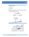
Possible locations for your PinPoint installed in a vehicle are in a trunk away from where luggage
or other items won’t be likely to dislodge it, under or in the console, or behind seats. Ensure the
location is secure both against abrupt movements of the vehicle and from other items coming into
contact with the modem.
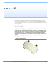
An optional accessory for your PinPoint is a mounting kit. The bracket is designed to snugly cra-
dle the modem and hold it in place where you need it.
Modem placement with diagrams of the mounting bracket can be found in the
Appendix, “Modem Placement” on page
54.
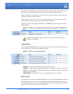
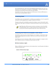
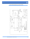
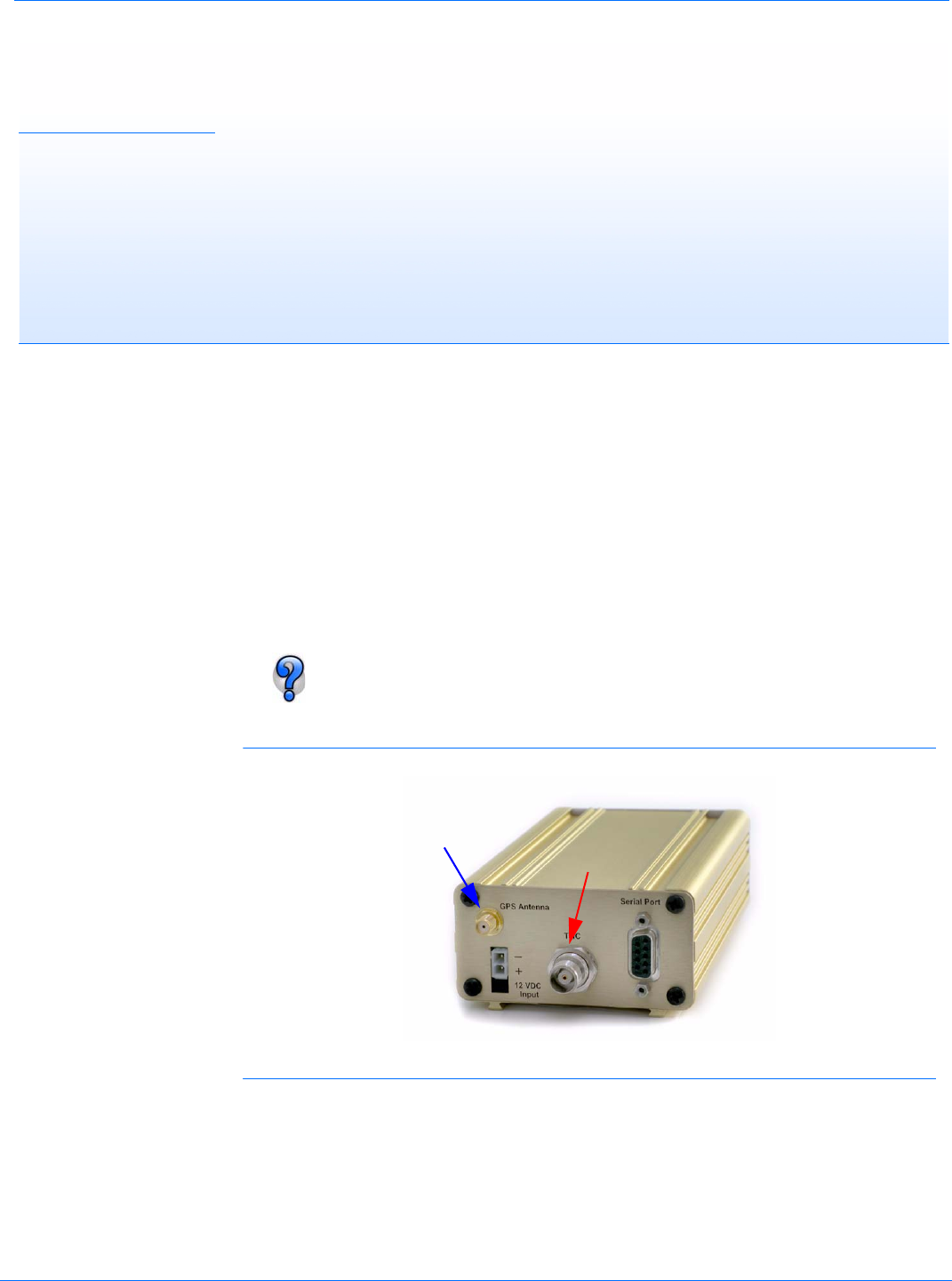
FIGURE 1. PinPoint connecters
Connecting the Antennas
Antennas selected should not exceed a maximum gain of 5 dBi under standard installation config-
uration. In more complex installations (such as those requiring long lengths of cable and/or multi-
ple connections), it’s imperative that the installer follow maximum dBi gain guidelines in
accordance with the FFC’s, Industry Canada’s, or your country’s radio communications regula
-
tory body’s regulations.
Cellular
GPS