


PinPoint EDGE/GPRS - User Guide, version 2.32 31
External Inputs & Power Control
When the switch is closed and with *PPINPUTEVT configured, a RAP report will be sent to the
destination IP address indicating that a contact closure has taken place (an external physical event
has occurred). See “RAP Configuration” on
page 40.
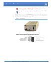
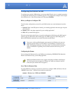
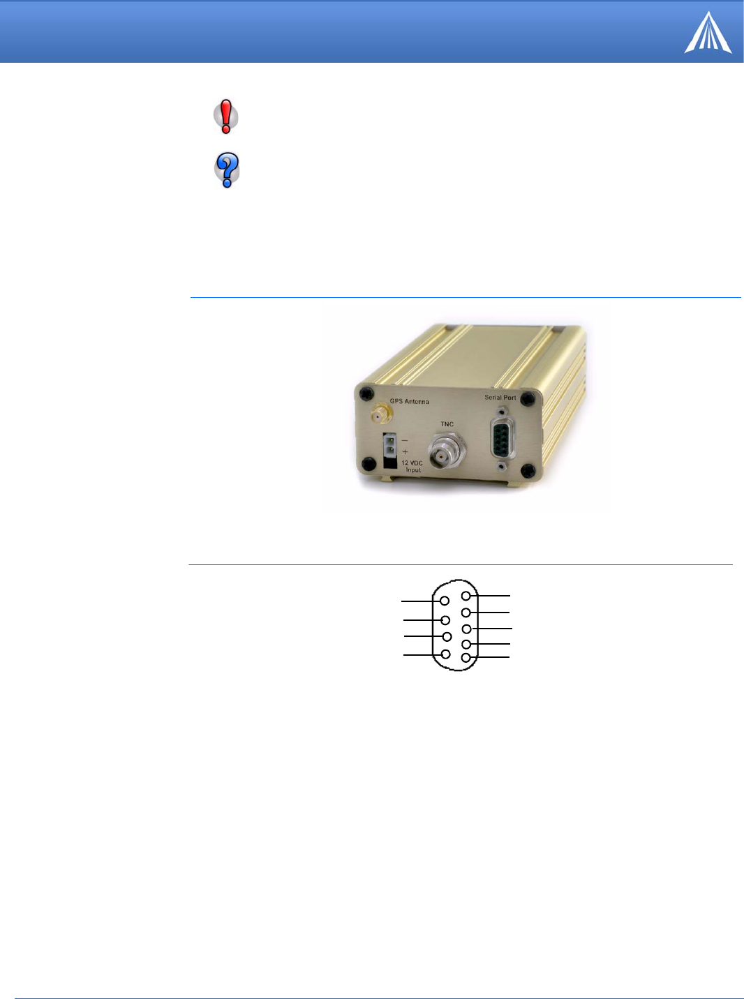
FIGURE 2. PinPoint back
Caution: Never apply voltage to the DTR or RTS inputs. DTR and RTS can
only be switched open or closed to ground.
You may be able to purchase a customizable serial cable to use with DTR and RTS
inputs. Contact your AirLink representative for more information.
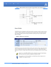
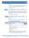
FIGURE 3. Serial Port Diagram : Female DB-9 DCE (not to scale)
5
4
3
2
1
9
8
7
6
< - > GND (Ground)
< - DTR Data Terminal Ready)
< - Rx (Receive)
- > Tx (Transmit)
- > DCD (Data Carrier Detect)
Unused
CTS (Clear to Send)
< -
RTS (Request to Send) - >
DSR (Data to Send) < -