


PinPoint EDGE/GPRS - User Guide, version 2.32 52
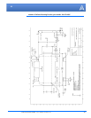
Hardware Installation
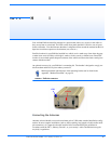
Your PinPoint can be used with either DC (available in most automobiles) or 110 AC (standard US
wall power) with the appropriate power adapter (available from AirLink).
The power cable positive lead should be connected to the battery or power source positive termi-
nal. The power cable negative lead should be connected to the battery or power source negative ter-
minal.
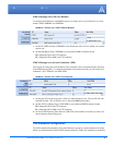
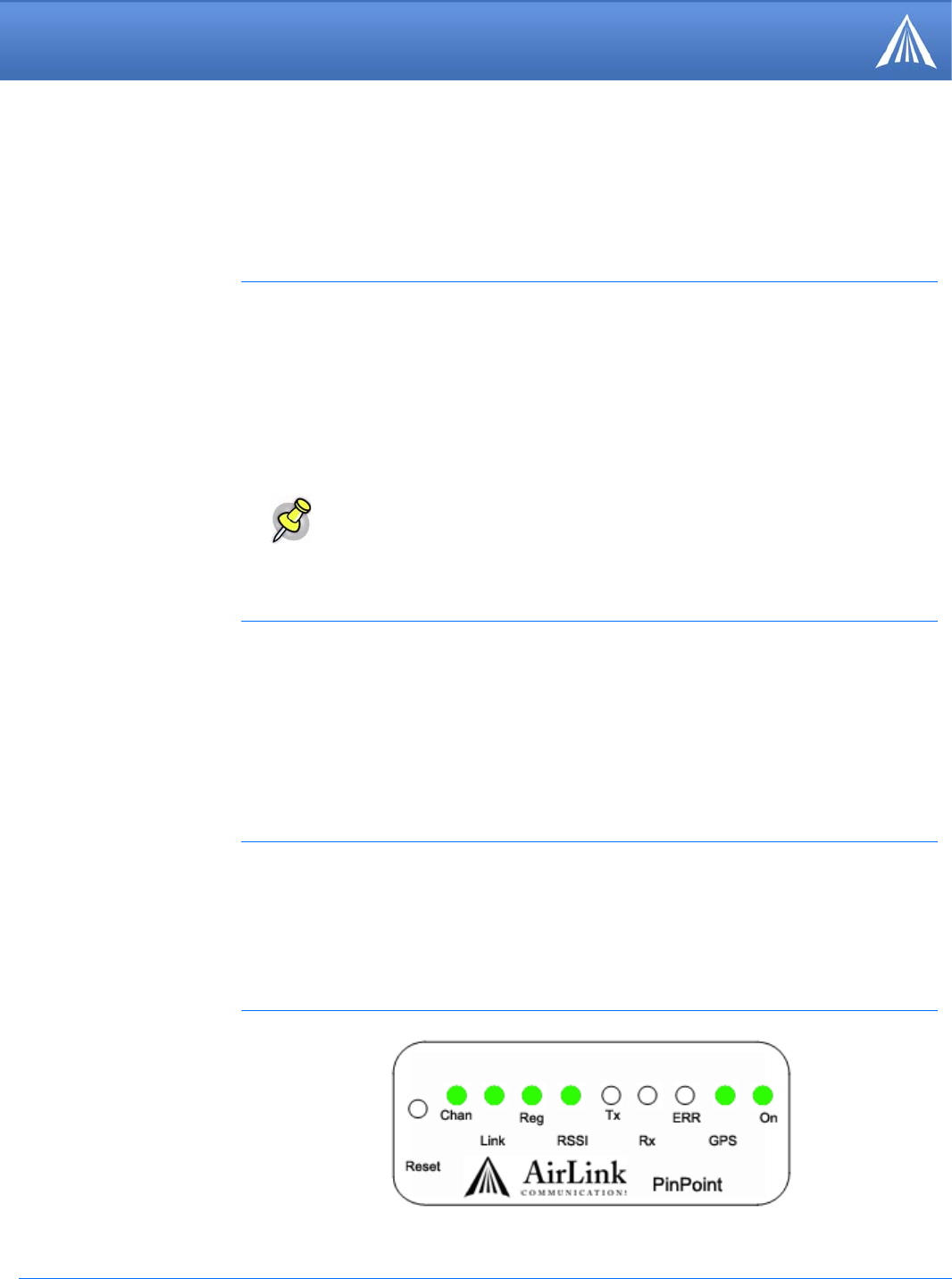
When your PinPoint is connected to power and an antenna, there is a specific pattern to the lights to
indicate its operation mode.
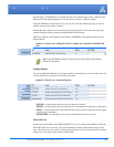
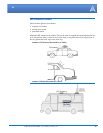
Your AirLink PinPoint will work with most Dual-Band PCS cellular antennas with a TNC con-
nector that works in the high and low frequencies of EDGE/GPRS . Connect the antenna or RF
cable directly to the antenna connector on the back of the PinPoint.
Your PinPoint will work with most standard active GPS antennas. Connect the GPS antenna or
cable directly to the threaded SMA connector.
Connecting Power
Note: When using a DC power source (such as a car battery or solar cell), AirLink
recommends placing a fuse (1-2 Amp) on the line close to the power source to pro
-
tect your power source from possible surges due to shorts or other line issues.
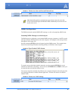
Connecting the PinPoint to a computer or other device
Your PinPoint’s serial port can be connected directly to most computers or other devices using a
standard straight through cable. If you have a DCE device, you will need a null modem or null
modem cable.
Your PinPoint can also be connected to a USB to serial device connected to a computer or other
device which does not have an available serial port but does have USB.
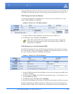
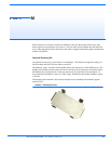
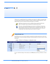
PinPoint Indicator Lights
FIGURE 2. PinPoint indicator lights