


Section 3
Operation
RPMSP & CSP70 User’s Manual 3-1
This section explains how to effectively operate the projector once it has been
installed. It is recommended that you read this section and familiarize yourself with
the components and the available menu options before you begin using your projector
for the first time.
Refer also to the Installation Guide
provided with your projector for installation and
setup information.
The projector’s modular architecture is best suited for control room and mission
critical environments where ease of servicing is a must and down time must be kept to
a minimum. A brief description of each module has been provided in this section.
Knowing your projector will help you in times where troubleshooting is necessary.
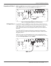
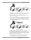
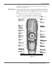
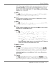
Figure 3.1. Identifying Projector Components
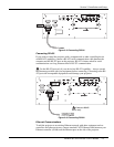
Projection Head Module (PHM)
The PHM module is the centermost module of the projector. It contains the projection
lens (0.7:1 or 1.16:1), IR sensor, color wheel, DMD and other optical components. It
also provides the electrical interfaces required to drive these components.
The PHM is connected to the adjacent DLM module. As an assembly, the two
modules are mounted to the 6-axis adjustment mechanism. With a quick changeover
in mounting brackets the PHM can be removed, rotated 90°, and re-mounted for rear
screen projection applications where a first surface optical mirror is used.
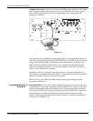
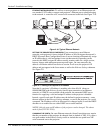
Dual Lamp Module (DLM)
The DLM connects to the adjacent PHM module by a specially designed coupling that
allows rotation of the PHM module only This module houses the two 100W UHP
lamps, two lamp drivers, a 390V high voltage power supply (HVPS) and cooling fans.
3.1 About the
Projector