


Section 3: Operation
RPMSP & CSP70-D100U User’s Manual 3-59
.
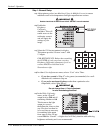
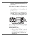
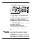
3. SET STARTING POINTS FOR ADJUSTMENT:
Set all blend widths to 0.
Go to “More” and set everything in the Edge Blending (2) menu to 50.
Figure 3.37. Set Starting Points for Each Projector
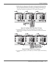
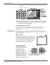
4. SET BLEND WIDTH: On one projector, increase the Blend Width for an overlapping
edge (for example, if the projector’s image is on left, its right edge overlaps the
adjacent image—adjust Right Blend Width). Use the same setting on the second
projector for this shared edge.
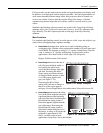
5. Re-adjust width (both projectors) until the overly bright band at the midpoint of the
overlapping blends disappears or just changes to very light gray. For the shared
edge, use the same Blend Width setting on each projector. If the best effect appears
to be between two settings, choose the wider setting for both projectors.
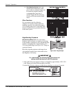
6.
CHECK BLEND: If the blended region appears too dark or light in relation to the rest
of the image:
Increase Blend Midpoint in both projectors to “lighten” the overall blend,
decrease to “darken” the overall blend.
Adjust Blend Shape in both projectors to fine-tune change the amount of mid-
gray intensity (as opposed to black/white) in the blend.
7. Repeat with remaining projectors / overlaps.
8. Check completed display wall with the desired external signal.
9. Adjust mechanical alignment if necessary to maintain perfect pixel-on-pixel
alignment over time.
In applications where you are projecting only white or light images, the Blend Width
may be slightly higher—set according to how much overlap you have between
images.
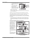
As an alternative to using a keypad, most projector functions can be controlled
remotely, typically at a controller such as a PC, via 1) simple bi-directional ASCII
messaging on an Ethernet or serial communication link or 2) a web interface or
“ChristieNET” on an Ethernet network.
VIA ASCII MESSAGING — Connect a serial link between your controller and the RS232
or RS422 port (recommended), or open an Ethernet socket (i.e., Telnet) between your
controller and the valid projector address. Valid ASCII codes and messages are
documented in the Christie Serial Communications document available at the Christie
website.
3.11 Remote Control
of the Projector