


Section 3: Operation
RPMSP & CSP70-D100U User’s Manual 3-21
.
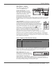
If some shimmer from a video or HDTV source persists, use the “Filter” control to
remove high-frequency noise from the signal.
H-Position
This option moves the image right or left within the area of available pixels.
NOTE: The value shown represents where the approximate center of the image lies in
relation to the total number of pixels available horizontally. This varies widely
according to the signal—watch the image while adjusting.
V-Position
This option moves the image up or down within the area of available pixels.
NOTE: The value shown represents where the approximate center of the image lies in
relation to the total number of pixels available vertically. This varies widely
according to the signal—watch the image while adjusting.
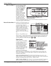
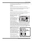
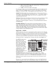
Advanced Size and Position
— SUBMENU
This submenu consists of the
following options:
ACTIVE INPUT WINDOW: This read-
only value indicates the current
size (i.e., area) of your displayed
data or “region of interest” as
defined by the blanking controls.
By default, the projector
automatically determines what
portion of its full resolution to use,
and pixels in the surrounding borders are turned off. You can also specify a specific
active input window size by adjusting one or more “Blank” settings. For example, if
you have blanked (cropped) 100 pixels from both the left and right edges of an
incoming source of 1400 x 1050, the remaining active input window will be reduced
to 1200 x 1050. When using SD or HD or a decoded video source at
INPUT 3 or INPUT
4, the default blanking of “0” defines an active input window of 720 x 483.
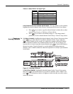
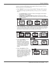
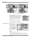
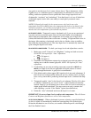
BLANKING (TOP, BOTTOM, LEFT, and
RIGHT):
Crop the image as desired so
that unwanted edges are removed from
the display (changed to black—see
right). Blanking defines the size of the
Active Input Window, or area of interest.
Range of adjustment depends on the
source resolution and other factors.
After adjustment of blanking it may be
necessary to perform a source switch.
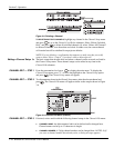
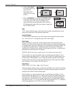
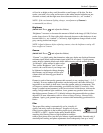
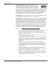
NOTE: Blanking a PIP image
resembles zoom (Figure 3.12). For
example, left Blanking zooms the right
side of the PIP image; Right Blanking
zooms the left side. There are no black
Figure 3.11. Blanking of a Primary Image