


Section 2: Installation and Setup
2-2 RPMSP & CSP70-D100U User’s Manual
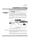
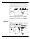
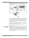
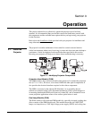
Connect the SYNC BNC input(s) first. Then connect the red, green and blue source
outputs to the
RED, GREEN, and BLUE BNCs on the INPUT 1 panel. If the source uses
sync-on-green, only the red, green, and blue connections are required. If the source
provides a composite sync output, connect it to the
SYNC input labeled HOR/COMP. If
the source provides separate horizontal and vertical sync outputs, connect horizontal
sync to the
SYNC input labeled HOR/COMP and connect vertical sync to SYNC input
labeled
VERT. See Figure 2.2.
Figure 2.2. Connecting RGB and Sync
NOTES: 1) If for some reason the projector fails to recognize a signal as an RGB
signal, specify this Color Space option within the Image Settings menu. See 3.5
Adjusting the Image. 2) To connect YPbPr signals–such as from DVDs or analog HDTV
sources–to
INPUT 1, use the red, green and blue BNCs as described in YPbPr Signals
(below).
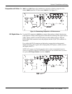
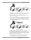
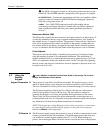
Connect a YPbPr signal (component video) to INPUT 1 or INPUT 2 as shown in Figure
2.3.
NOTES: 1) If, for some reason, the projector fails to recognize a YPbPr signal,
specify this Color Space option within the Image Settings menu. See 3.5, Adjusting
the Image. 2) Do not connect digital
component signals (known as YCbCr) to INPUT
1
. Install an appropriate optional module in INPUT 5 for this.
Figure 2.3. Connecting YPbPr sources
YPbPr Signals '
(COMPONENT VIDEO)