


Section 3: Operation
3-40 RPMSP & CSP70-D100U User’s Manual
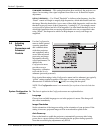
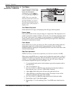
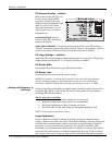
Test Pattern
Choose the desired internal test
pattern to display, or select OFF
to turn off a test pattern.
Alternatively, use the
Test
key
for cycling through test patterns.
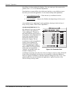
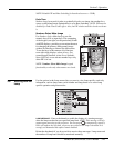
NOTE: There is a center line
(both horizontal and vertical) in
the Edge Blending test pattern.
The intersection of these lines is
the true center of the projector’s
display area.
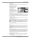
Test Pattern Grey Level
Set the desired level of grey for displaying in the full gray field test pattern.
Freeze Image
Enter a check mark to freeze (stop) an image on a single frame. This diagnostic tool is
useful if you need to examine in detail a still version of an incoming image that cannot
be “frozen” at the source. For example, in moving images it is sometimes difficult to
observe artifacts such as external deinterlacing/resizing and signal noise. Remove the
checkmark to return back to normal.
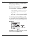
Color Enable
Select which color or colors you want to see. This is useful while working with color
temperature, input levels or other special setup parameters. Colors can also be
enabled/disabled by entering the corresponding function code listed on the back of the
standard remote keypad.
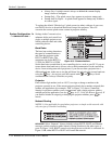
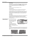
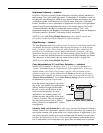
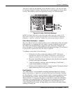
Odd Pixel Adjustment
NOTES: 1) Factory-set and rarely required by user. 2) Source must be >90 MHz.
When using certain RGB sources, you may need to adjust the normal gain or offset of
odd pixels in relation to even pixels. This will smooth out very narrow (1-pixel wide)
“checks” or vertical stripes that indicate adjacent “on” and “off” pixels. Using the
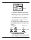
Level Detector simplifies this process (see Figure 3.22):
1. Use an external analog native-sized continuous grayscale test pattern with at
least 256-levels.
2. Turn “Level Detector” on.
3. Set “Level Value” to ~200. The image should now be black-and-white (or
black-and-one color, if you use “Color Enable” function).
4. Adjust offset. Half of the pixels will move, the other half will not.
5. Adjust until the two transition regions overlap. The stripe of noise will be
minimized, defined by the value in the slidebar.
6. Set “Level Value” to ~800. The image should now be black-and-white.
7. Repeat Steps 4 and 5, but adjusting gain.
8. Repeat Steps 3-7 for all remaining colors. Your RGB source should now be
OK.
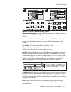
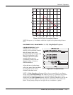
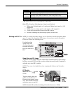
System Configuration
'
DIAGNOSTICS / CALIBRATION