


Section 2
Installation & Setup
RPMSP & CSP70-D100U User’s Manual 2-1
This section includes information on the setup and connection of various sources to
the projector. Sources should only be connected after the projector has correctly been
installed. For mechanical installation and first-time setup instructions, refer to the
separate Installation Guide
provided in the User’s Kit.
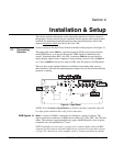
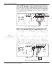
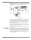
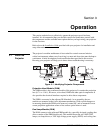
Sources connect to the Input Panel located at the back of the projector. See Figure 2.1.
The upper right corner (
INPUT 1) typically accepts an RGB signal from an external
analog RGB source, or it can also be used for YPbPr signals or additional video
sources. Just beside these BNCs, the DVI-I connector (
INPUT 2) accepts digital or
analog display signals from a computer. Connect analog composite video at
INPUT 3
or S-video at
INPUT 4 from devices such as VCRs, laser disc players or DVD players.
There are also several optional interfaces available for connecting other sources—
these interfaces slide into the remaining unused option slot, and can be done while the
projector is running.
Figure 2.1. Input Panel
NOTES: 1) See Section 6, Specifications for details regarding compatible inputs. 2)
Use high quality shielded cables only for all connections.
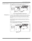
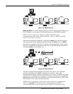
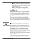
INPUT 1 consists of 5 BNCs (connectors) for linking to a variety of sources. The
typical connection would be to an RGB source such as a PC, Mac, DEC, Sun, SGI and
others. This projector supports multiple sync types with RGB signals: sync-on-green,
composite sync, and separate H & V syncs.
NOTE: Depending on your source, you may need a custom adapter cable with BNC
connectors at the projector end and a different type of connector at the other (such as
a 15-pin "D" connector for some computer sources). Contact your dealer for details.
2.1. Connecting
Sources
RGB Si
g
nals
'