Chapter 5 Troubleshooting the System Hardware
Identifying Problems Using Trouble Indicators and Status LEDs
5-20
Cisco Wide Area Application Engine 7326 Hardware Installation Guide
OL-6831-02
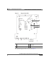
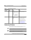
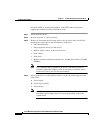
Note Depending on your device model, these items might appear in a different order on
the LED panel than what is shown in the figure.
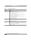
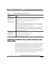
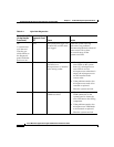
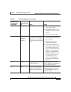
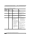
Table 5-3 Diagnostic Panel LEDs
Diagnostic Panel LED Description
POWER SUPPLY 1 The power supply in bay 1 failed.
POWER SUPPLY 2 The power supply in bay 2 failed.
VRM An error occurred on microprocessor voltage regulator module
(VRM).
CPU One or both microprocessors failed, or one is seated in the wrong
socket.
NON-RED Device power supplies are no longer redundant (applicable only with
the redundant power feature).
MEMORY Memory failure. One or more dual inline memory modules (DIMMs)
failed.
OVER SPEC The system has shut down because of a system overload condition.
DASD The SCSI backplane or a device connected to a SCSI bus failed.
DASD devices are not supported in Cisco ACNS software.
NMI Nonmaskable interrupt occurred.
PCI BUS A An error occurred on an adapter in PCI-X slots 1 or 2 or one of the
integrated PCI devices on the system board.
ISMP BUS Service processor failure.
PCI BUS B An error occurred on an adapter in PCI-X slots 3 or 4.
FAN A fan (1, 2, 3, 4, 5, 6, 7, or 8) failed or is operating slowly.
CPU/VRM MISMATCH The service processor detected a CPU or VRM mismatch.
PCI BUS C An error occurred on an adapter in PCI slot 5.
TEMP System temperature exceeded maximum rating.


