Chapter 5 Troubleshooting the System Hardware
Symptoms and Solutions
5-34
Cisco Wide Area Application Engine 7326 Hardware Installation Guide
OL-6831-02
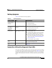
When checking the diagnostic panel LEDs, note the following information:
• If a diagnostic panel LED is on and the front panel system error LED is off,
there is probably an LED problem. Run the LED diagnostics.
• To locate the LEDs on the system board, see Figure 5-1 on page 5-17.
• Check the system error log for additional information before replacing a
component. (See the “Viewing Error Logs” section on page 5-10.)
• The DIMM error LEDs, microprocessor error LEDs, and VRM error LEDs
on the system board go off when the system is powered down.
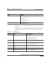
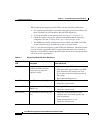
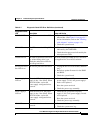
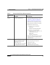
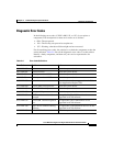
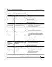
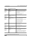
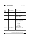
Table 5-7 provides the diagnostic panel LED error definitions. The third column
lists one or more suggested actions or components that need to be reseated or
replaced. Use this table to identify possible causes for the error message and then
call your service representative.
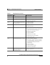
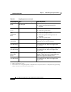
Table 5-7 Diagnostic Panel LED Error Definitions
Diagnostic Panel
LED Description Cause and Action
All LEDs off Check system error log for error
condition and then clear the
system error log when the
problem is found.
1. System error log is 75% full; clear the log.
2. PFA alert; check log for failure; clear PFA
alert; disconnect AC power for at least
20 seconds, reconnect, and then power up
the system.
3. Run Light Path Diagnostics.
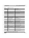
Fan LED on The LED next to the failing fan is
on.
1. Failing fan.
2. Check the system board.
Memory LED on The LED next to the failing
DIMM is on.
1. Failing DIMM.
2. Check the system board.
CPU LED on The LED next to the failing CPU
is on.
1. Verify that all microprocessors have
identical cache sizes, dock speeds, and
clock frequencies.
2. Check microprocessor 1 or 2.
3. Check the system board.


