


2-218
Catalyst 6500 Series Switch Command Reference—Release 8.4
OL-6244-01
Chapter 2 Catalyst 6500 Series Switch and ROM Monitor Commands
l2trace
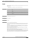
The Layer 2 trace feature is not supported when multiple devices are attached to one port through hubs
(for example, multiple CDP neighbors detected on a port). When more than one CDP neighbor is
detected on the port, l2trace is aborted.
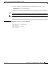
If you specify the IP address of the source and destination systems instead of the MAC addresses, the switch
looks at the ARP table to determine the IP address to MAC address mapping of the source and destination
systems. If an ARP entry exists for the specified IP address, the corresponding MAC address is used. If no
matching ARP entry exists, the system does an ARP query and tries to resolve the IP address. If this is the
case, a restriction is imposed that requires the source and destination systems to be in the same subnet as the
switch in order for the ARP query to be resolved.
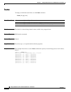
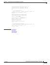
Examples This example shows how to display the Layer 2 packet path for a specified source and destination MAC
address:
Console> (enable) l2trace 00-01-22-33-44-55 10-22-33-44-55-66 detail
l2trace vlan number is 10.
00-01-22-33-44-55 found in C5500 named wiring-1 on port 4/1 10Mb half duplex
C5500: wiring-1: 192.168.242.10: 4/1 10Mb half duplex -> 5/2 100MB full duplex
C5000: backup-wiring-1: 192.168.242.20: 1/1 100Mb full duplex -> 3/1-4 FEC attached
C5000: backup-core-1: 192.168.242.30: 4/1-4 FEC attached -> 1/1-2 GEC attached
C6000: core-1: 192.168.242.40: 1/1-2 GEC attached -> 2/1 10MB half duplex.
10-22-33-44-55-66 found in C6000 named core-1 on port 2/1 10MB half duplex.
Console> (enable)
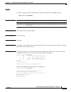
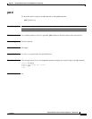
This example shows how to display the Layer 2 packet path for a specified source and destination IP
alias:
Console> (enable) l2trace user-1-pc user-2-pc detail
Mapping IP address to MAC Address
user-1-pc -> 00-01-22-33-44-55
user-2-pc -> 10-22-33-44-55-66
l2trace vlan number is 10
00-01-22-33-44-55 found in C5500 named wiring-1 on port 4/1 10Mb half duplex
C5500: wiring-1: 192.168.242.10: 4/1 10Mb half duplex -> 5/2 100MB full duplex
C5000: backup-wiring-1: 192.168.242.20: 1/1 100Mb full duplex -> 3/1-4 FEC attached
C5000: backup-core-1: 192.168.242.30: 4/1-4 FEC attached -> 1/1-2 GEC attached
C6000: core-1: 192.168.242.40: 1/1-2 GEC attached -> 2/1 10MB half duplex.
10-22-33-44-55-66 found in C6000 named core-1 on port 2/1 10MB half duplex.
Console> (enable)
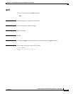
This example shows how to display a summary of Layer 2 packet path information for a specified source
and destination IP address:
Console> (enable) l2trace 9.7.0.7 9.7.0.6
Starting L2 Trace
sc0 :9.7.0.7 : 3/7
4/16 :9.7.0.2 : 4/10
Console> (enable)