


2-871
Catalyst 6500 Series Switch Command Reference—Release 8.4
OL-6244-01
Chapter 2 Catalyst 6500 Series Switch and ROM Monitor Commands
show environment
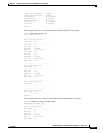
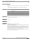
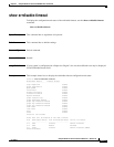
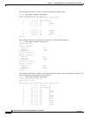
This example shows how to display connector rating information:
Console> show environment connector
Chassis connector rating : 756.00 Watts (18.00 Amps @42V)
Slot connector rating :
Slot CardType ConnectorRating
Watts A @42V
---- ------------------- -------- ------
3 WS-X6724-SFP 693.00 16.50
6 WS-X6K-SUP3-BASE 693.00 16.50
7 FI_WS_X6348_RJ45 693.00 16.50
9 WS-X6704-10GE 756.00 18.00
Console>
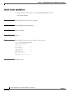
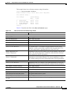
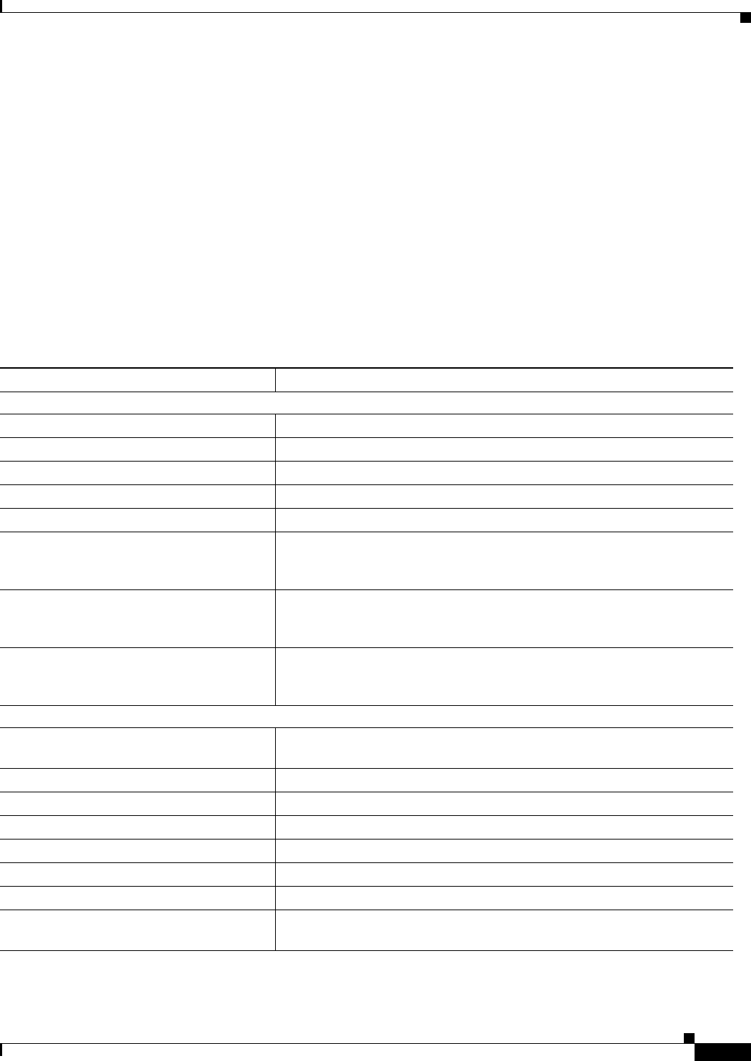
Table 2-32 describes the fields in the show environment output.
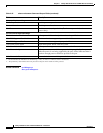
Table 2-32 show environment Command Output Fields
Field Description
Environmental Status
1
PS1: and PS2: Power supply status.
PS1 Fan: and PS2 Fan: Power supply fan status.
Chassis-Ser-EEPROM: Chassis serial EEPROM status.
Fan: Fan status.
Clock A: and Clock B: Clock A and B status.
VTT1:, VTT2:, and VTT3: VTT module status. VTT modules are power monitors for the chassis
backplane. A minor system alarm is signalled when one of the three VTTs
fails, and a major alarm is signalled when two or more VTTs fail.
Intake Temperature and
Exhaust Temperature
Temperature of the air flow as it enters, goes over the modules, and exits the
chassis. The current temperature is listed first, with the minor and major
alarm temperatures listed in parentheses.
Device 1 Temperature and
Device 2 Temperature
The devices are additional temperature sensors measuring the internal
temperature on each module indicated. The current temperature is listed
first, with the warning and critical alarm temperatures listed in parentheses.
Chassis Modules
VTT1:, VTT2:, and VTT3: Temperature of the VTT modules. The current temperature is listed first,
with the minor and major alarm temperature settings listed in parentheses.
PS1 Capacity: and PS2 Capacity: Power supply capacity.
PS Configuration: Power supply configuration.
Total Power Available: Total available power.
Total Power Available for Line Card Usage: Total power available for module use.
Total Power Drawn From the System: Total power drawn from the system.
Remaining Power in the System: Remaining power in the system.
Configured Default Inline Power allocation
per port:
Configured default inline power allocation per port.