


CHAPTER 11: MELODY ASSEMBLER
274 EPSON S5U1C63000A MANUAL
(S1C63 FAMILY ASSEMBLER PACKAGE)
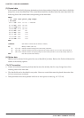
(3) Control data
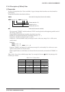
In the control data field, the jump destinations (main data numbers) from the main data in which the
jump bit is set are described here. The control data should be described after the main data field. The
following shows the control data corresponding to the main data.
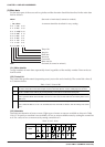
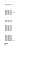
MAIN
; no. cntl note pitch jump tempo
; m0 test
0 1 7 G5 0 0
<1> <5> ← Data flow
1 1 6 F5 0 0 <2> <6>
2 1 5 D5# 0 0 <3> <7>
3 2 4 RR 1 0 <4> <8>
4 0 3 E5 0 1 <9>
5 1 2 E5 0 1 <10>
6 1 1 D5 0 1 <11>
7 1 0 C5 0 1 <12>
8 3 0 RR 1 1 <13>
END
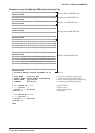
CONTROL
Start mark of control data (It cannot be omitted.)
m0 Melody number (m0–m15)
0 <1>–<4> Indicates that the m0 begins from the melody data No.0
0 <5>–<8> Indicates that the music flow jumps from the melody data No.3 (<4>) to the melody data No.0.
4 <9>–<13> Indicates that the second play jumps from the melody data No.3 (<8>) to the melody data No.4.
END End mark (It cannot be omitted.)
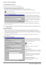
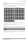
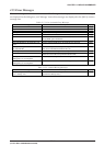
(4) Option data
Options can be selected in the option list area of the [MLA] window. Refer to the Technical Manual for
details of the melody options.
11.4.5 Precautions
•Create scores before inputting melody data because the melody data No. may change later when
inserting data in the main data.
• The data fields can be described in any order. However, control data must be placed after main data
(it is not necessary to continue).
• Data parameters must be separated with one or more spaces or tabs (eg., 0 1 7 G5 0 0).