


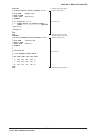

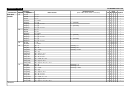

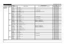
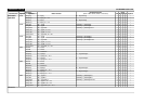
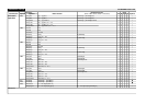
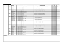
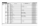
Instruction List (1)
S1C63000 Core CPU
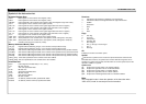
Symbols in the Instruction List
Registers/Register Data
%A, A: Data register A or the contents of the register (4 bits)
%B, B: Data register B or the contents of the register (4 bits)
%BA, BA: Data register BA or the contents of the register (8 bits, the B register is high-order 4 bits)
%X, X: Index register X or the contents of the register (16 bits)
%XH, XH: Index register XH or the contents of the register (high-order 8 bits of the X register)
%XL, XL: Index register XL or the contents of the register (low-order 8 bits of the X register)
%Y, Y: Index register Y or the contents of the register (16 bits)
%YH, YH: Index register YH or the contents of the register (high-order 8 bits of the Y register)
%YL, YL: Index register YL or the contents of the register (low-order 8 bits of the Y register)
%F, F: Flag register F or the contents of the register (4 bits)
%EXT, EXT: Extension register EXT or the contents of the register (8 bits)
%SP1, SP1: Stack pointer SP1 or the contents of the stack pointer (16 bits, setting data = SP1(9:2))
%SP2, SP2: Stack pointer SP2 or the contents of the stack pointer (16 bits, setting data = SP2(7:0))
PC: Contents of the program counter PC (16 bits)
Memory/Addresses/Memory Data
[%X], [X]: Register indirect addressing using X, or the contents of the specified memory
[%Y], [Y]: Register indirect addressing using Y, or the contents of the specified memory
[00addr6]: 6-bit absolute addressing with addr6, or the contents of the specified memory (0x0000–0x003F)
[FFaddr6]: 6-bit absolute addressing with addr6, or the contents of the specified memory (0xFFC0–0xFFFF)
[00imm8]: 8-bit absolute addressing with imm8, or the contents of the specified memory (0x0000–0x00FF)
[FFimm8]: 8-bit absolute addressing with imm8, or the contents of the specified memory (0xFF00–0xFFFF)
[%SP1], [SP1]: 16-bit stack specification or the contents of the stack address
[%SP2], [SP2]: 4-bit stack specification or the contents of the stack address
Immediate Data
immN: N-bit unsigned immediate data (N = 2, 4, 6 or 8)
i7–i0: Bit data of immN
n4: 4-bit radix specification data
n3–n0: Bit data of n4
sign8: Signed 8-bit immediate data
s7–s0: Bit data of sign8
addr6: 6-bit absolute address
a5–a0: Bit data of addr6
00addr6: An address (0x0000–0x003F) specified with addr6
FFaddr6: An address (0xFFC0–0xFFFF) specified with addr6
Functions
←: Indicates that the right item is loaded or set to the left item.
↔: Indicates that data is exchanged between the right and left items.
+: Addition
-: Subtraction
∧: AND
∨:OR
∀: XOR
Flags
Z: Zero flag
C: Carry flag
I: Interrupt flag
E: Extension flag
–: Not changed
↔: Set (1), reset (0) or not changed
1: Set (1)
0: Reset (0)
Clk
Indicates the number of execution cycles.
Symbol
● Indicates that a symbol can be used for the operand instead of an 8-bit or 6-bit
immediate data. However, the symbol value must be within the range that can be
specified. If a symbol mask is listed, the instruction can use the symbol mask for the
operand in addition to a symbol.
Symbol mask
@l: Acquires the low-order 8 bits of an absolute address.
@h: Acquires the high-order 8 bits of an absolute address.
@rl: Acquires the low-order 8 bits of a relative address.
@rh: Acquires the high-order 8 bits of a relative address.
@xh: Acquires the inverted high-order 8 bits of an absolute address.
Note
The "Extended function" shows the operation of the instruction when
"LDB %EXT, imm8" is executed prior to the instruction.