


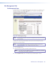
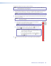
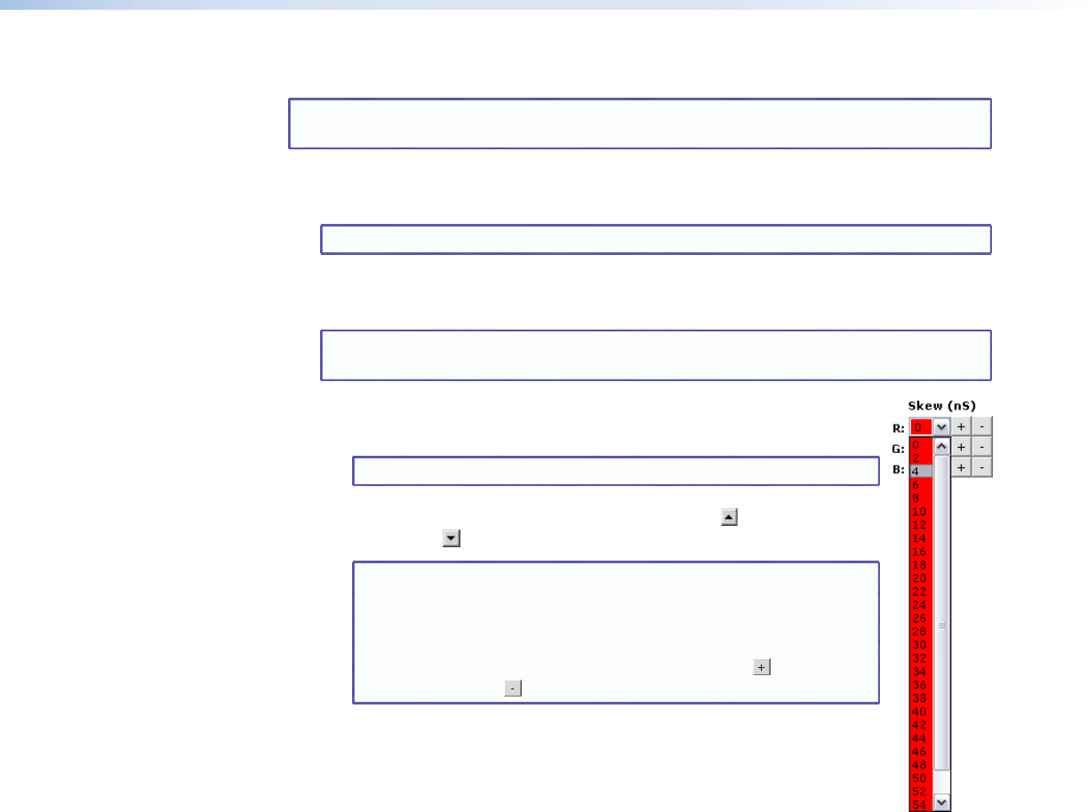
Change skew setting for an input or output as follows:
NOTE: For best results, set all three skew values to 0 ns (see steps 2a and 2b below)
before adjusting for misconvergence.
1. Use UTP cable test equipment or examine the displayed video image with a critical eye
to determine which video signal, red, green, or blue, is most shifted to the left.
NOTE: A crosshatch test pattern is ideal for evaluating pair skew.
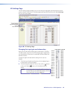
2. Monitor the displayed image. Increase the skew setting for the left-shifted video signal 2
ns at a time as follows:
NOTE: The skew compensation function cannot shift a video plane farther left
than the 0 ns setting.
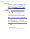
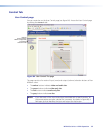
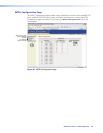
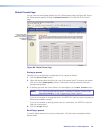
a. Click drop box for the desired input or output and the desired
video plane. A drop-down scroll box appears.
NOTE: The red video plane is selected at right.
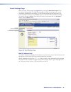
b. Click and drag the slider or click on the scroll up button or the
scroll down button until the desired value is visible.
NOTES: • A 2-nanosecond adjustment is very fine. Up to
10 nanoseconds of delay may be necessary before you
detect a change in the display.
• As an alternative to step 2, or to watch a display as
you make adjustments, click on the up button or
down button.
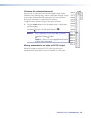
3. If either of the other video signals is misconverged, repeat steps 2a and
2b.
MTPX Plus Series • HTML Operation 140