


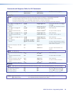
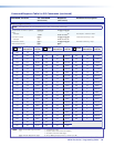
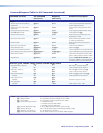
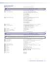
Command/Response Table for SIS Commands (continued)
Command Function
SIS Command
(Host to Unit)
Response
(Unit to Host)
Additional description
Resets
Reset all input level and peaking
adjustments
E
ZT
}
Zpt
]
Clear all level and peaking adjustments
to their default (0) values.
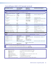
Reset all input and output skew
adjustments
E
ZK
}
Zpk
]
Clear all input and output skew values
to 0 ns.
Reset global presets and names
E
ZG
}
Zpg
]
Clear all global presets and their names.
Reset one global preset
EX2#
ZG
}
Zpg
X2#]
Clear global preset
X2#
.
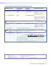
Reset audio input levels
E
ZA
}
Zpa
]
Reset all audio input levels (gain and
attenuation) to 0 dB.
Reset audio output levels
E
ZV
}
Zpv
]
Reset all audio output levels (volume)
to 100% (no attenuation).
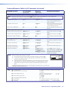
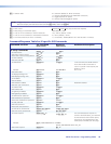
Reset all mutes
E
ZZ
}
Zpz
]
Reset all audio or RS-232 outputs to
unmuted.
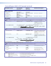
Reset room map (outputs)
E
ZR
}
Zpr
]
Clear all room definitions.
Reset individual room
EX2%
ZR
}
Zpr
X2%]
Delete room
X2%
.
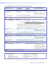
Reset all room presets and names
E
ZP
}
Zpp
]
Clear an individual room preset and name.
Reset individual room preset and name
EX2%
*
X2#
ZP
}
Zpp
X2%
*
X2#]
Clear an individual room preset and name.
Reset whole switcher
E
ZXXX
}
Zpx
]
Clear all ties and presets, reset all audio
gains to 0 dB, and reset volume to 100%.
Absolute reset
E
ZQQQ
}
Zpq
]
Similar to Reset whole switcher, plus
clear the IP address to 192.168.254.254
and subnet mask to 255.255.000.000.
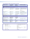
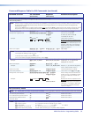
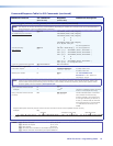
View ties, gain, volume, mutes, presets, and DIP switch status
Read RGB
(video) output tie
X@
&
X!]
RGB input
X!
is tied to output
X@
.
Example:
5&
12
]
Input 12 RGB is tied to output 5.
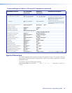
Read video output tie
X@
%
X!]
RGB input
X!
is tied to output
X@
.
Example:
7%
02
]
Input 2 video is tied to output 7.
Read audio output tie
X@
$
X!]
Audio input
X!
is tied to output
X@
.
Example:
3$
06
]
Input 6 audio is tied to output 3.
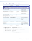
View output volume
X1*
V
X1(]
Example:
7V
55
]
Volume for output 7 is 55%.
View input gain
X*
G
X2!]
Example:
4G
-02
]
Audio input 3 level is -2 dB.
NOTE: X! = Input number 00 – (maximum number of inputs for your model)
X@ = Output number 01 – (maximum number of outputs for your model)
X* = Input number 01 – (maximum number of inputs for your model)
X1* = Local audio output number 1 – 2 (MTPX Plus 128)
1 – 4 (matrix sizes 1616 and smaller)
1 – 8 (matrix sizes 1632 and larger)
X1( = Volume adjustment range 0 – 64 (1 dB/step except for 0-to-1, which is 22 dB)
X2! = Numeric dB value –18 to +24 (45 steps of gain or attenuation) (Default = 0 dB)
X2# = Global or room preset # 01 - 32 (global) or 01-10 (room)
X2% = Room # (for room presets) 10 max. (each can have up to 10 presets (X2#s) assigned
MTPX Plus Series • Programming Guide 88