


Command/Response Table for SIS Commands (continued)
Command Function
SIS Command
(Host to Unit)
Response
(Unit to Host)
Additional description
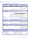
View ties, gain, volume, mutes, presets, and DIP switch status (continued)
View output mutes
E
VM
} X2&
1
X2&
2
...
X2&
n
Mut
]
Each
X2&
response is the mute status of
an output: left = output 1,
right = output n. n = the highest
output number for this model.
Example (MTPX Plus 3216):
E
VM
}
Mut0220200002202000
]
Output 1 is unmuted, output 2 video
is muted, output 3 video and audio are
muted, and output 4 audio is muted.
Outputs 5 through 8 are not present
on this switcher.
NOTE: The “Mut” portion of the response appears only when the switcher is in Verbose mode 1 or 3 (see the Set verbose mode SIS
command on page 95).
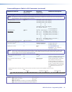
View video global preset
configuration
EX2#
*
X@
*1VC
} X!
n
•
X!
n+1
•
X!
n+1
•
X!
n+2
•...•
X!
n+15
•Vid
]
Show the video configuration for
preset
X2#
. Show the input tied to
16 sequential outputs, starting from
output
X@
.
Command description:
Response description:
preset #*starting output # (StO#)*1(=video)VC
input # (I#) tied to StO#•I# tied to StO#+1•I# tied to StO#+2• ... •I# tied to StO#+15•Vid
]
NOTES: • The starting output number (
X@
) should always be “1” for matrix sizes of 16 outputs or smaller.
•
EX2#
*
X@
*1VC
}
where
X2#
= 0 returns the current video configuration.
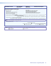
Example (MTPX Plus 168):
E
3*1*1VC
}
1Output:
Response = tied input:
input 12 tied to output 3
2345678
no tied input
input 8 tied to output 4
13 14 15 1609 10 11 12
outputs do not exist
•--•--•--•--•--•--•--•--•
08•08•12•08•08•11•00•00•
•Vid
Each position shown in the response is an output: left = starting output (1), right = starting output
+15 (16). (Outputs 9 through 16 are not present on the MTPX Plus 168.) The number in each
position is the input tied to that output.
In this example, preset 3, video input 8 is tied to outputs 1, 2, 4, and 5; input 12 is tied to output 3;
and input 11 is tied to output 6. No inputs are tied to outputs 7 and 8.
NOTE: X! = Input number 00 – (maximum number of inputs for your model)
X@ = Output number 01 – (maximum number of outputs for your model)
X2# = Global or room preset # 01 - 32 (global) or 01-10 (room)
X2& = Audio or RS-232 mute: 0 = no mutes 2 = audio or RS-232 mute
MTPX Plus Series • Programming Guide 89