


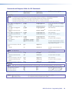
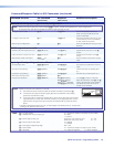
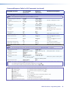
Command/Response Table for SIS Commands (continued)
Command Function
SIS Command
(Host to Unit)
Response
(Unit to Host)
Additional description
Audio/RS-232 TP input (wire pair 3 and 6) configuration
NOTE: The RS-232 output insert ports, when enabled (
EX%
*1Lrpt
}
), override the audio/RS-232 TP input configurations.
For the MTPX Plus 128, these commands are valid for inputs 5 through 12 only.
Configure input as audio
X*
*0\ Typ
X*
*0
]
Define the audio/RS-232 input as
audio, such as provided by an MTP
15HD A transmitter.
Configure input as RS-232
X*
*1\ Typ
X*
*1
]
Define the audio/RS-232 input as serial
communications, such as provided by
an MTP 15HD RS transmitter.
Read TP input configuration
X*
\
X$]
Show the audio/RS-232 wire pair input
definition.
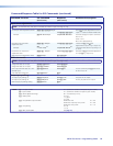
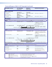
RS-232 output inserts enable
Disable an RS-232 output insert port
EX%
*0Lrpt
}
Lrpt
X%
*0
]
Disable the RS-232 insert on the
X%
output.
Enable an RS-232 output insert port
EX%
*1Lrpt
}
Lrpt
X%
*1
]
Enable the RS-232 insert on the
X%
output.
Read RS-232 output insert status
EX%
Lrpt
} X^]
Show the status of the RS-232 output
insert.
Input signal level/peaking and auto calibrate
Set input signal level
EX*
*
X&
Ipek
}
Ipek
X*
*
X&]
Set a specific pre-peak level for the TP
input.
Increment input peaking
EX*
+Ipek
}
Ipek
X*
*
X&]
Increase the input pre-peaking level
by 1
Decrement input peaking
EX*
-Ipek
}
Ipek
X*
*
X&]
Decrease the pre-peaking level by 1.
Read input peaking setting
EX*
Ipek
} X&]
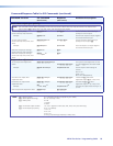
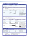
Execute auto calibration
EX*
*0AADJ
}
Aadj
X*
*2
]
{start}
Qik
]
{tie creation}
Aadj
X*
*
X(]
{finished}
Ipek
X*
*
X&]
{new value}
Tie input
X*
to output 1 and auto
adjust the peaking on input
X*
. The
X(
value in the response reports whether
the adjustment value was within or
outside of the threshold.
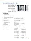
NOTES: • Before issuing the auto calibration command:
1. Disconnect the power and RJ-45 cables at the MTP transmitter connected to
X*
.
2. Connect the two cables to the MTP signal generator (included with most models,
optional for the MTPX Plus 128).
3. If the input cable is longer than 300 feet (90 m), place the Pre-Peak switch on the MTP
signal generator to on (up when the RJ-45 connector on the signal generator is to the
right as shown at right). If the cable is shorter than 300 feet (90 m), place the switch
down.
• The MTP signal generator does not work on cable lengths over 400 feet (120 m). Set the level/
peaking to its maximum value of 255.
Pre-Peak
is on
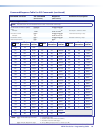
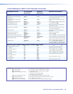
NOTE: X# = TP input number 01 – (maximum number of TP inputs for your model)
X$ = Audio/RS-232 wire pair input type 0 = audio
1 = RS-232
X% = RS-232 output insert port MTPX Plus 128, 168, 816, 1616 01 – 08
MTPX Plus 1632, 3216, 3232 01 – 16
X^ = RS-232 output insert status 0 = disabled
1 = enabled
X& = Input signal level/peaking range 000 – 255
X* = Input number 01 – (maximum number of inputs for your model)
X( = Threshold 0 = outside of threshold 1 = within threshold
MTPX Plus Series • Programming Guide 81