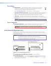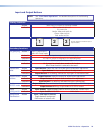
Reset Button
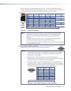
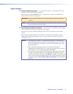
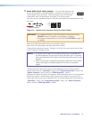
l Reset button — The Reset button initiates two levels of reset to the matrix
RESET
switcher. For two different reset levels, press and hold the button while the
switcher is running or while you power up the switcher.
See “Rear Panel Operations” in the “Operation” section for details.
• Rear panel (mode 5) system reset — Press and hold the Reset button until the Reset
LED blinks three times (approximately 9 seconds), then release the button and push it
again. This reset clears all ties and presets and resets all audio gains to 0 dB.
• Hard reset — Press and hold the Reset button while powering up the switcher to
perform all of the mode 5 reset functions and restore the switcher to the default factory
conditions.
NOTE: Hard reset does not clear the current configuration.
Power Connection
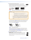
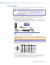
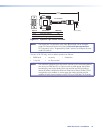
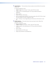
m AC power connector — Plug a standard IEC power cord into this connector to
connect the switcher to a 100 VAC to 240 VAC, 50 or 60 Hz power source.
WARNING: The power connector is wired double pole with neutral fusing.
Front Panel Configuration Port
This front panel configuration port serves a similar communications function as the rear
panel Remote port, but it is easier to access than the rear port after the matrix switcher has
been installed and cabled.
NOTES: • The Configuration port is independent of the rear panel Remote port and is
not affected by changes to the protocol of the rear panel port.
• A front panel Configuration port connection and a rear panel Remote port
connection can both be active at the same time.
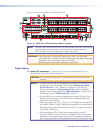
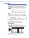
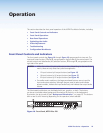
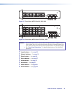
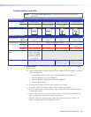
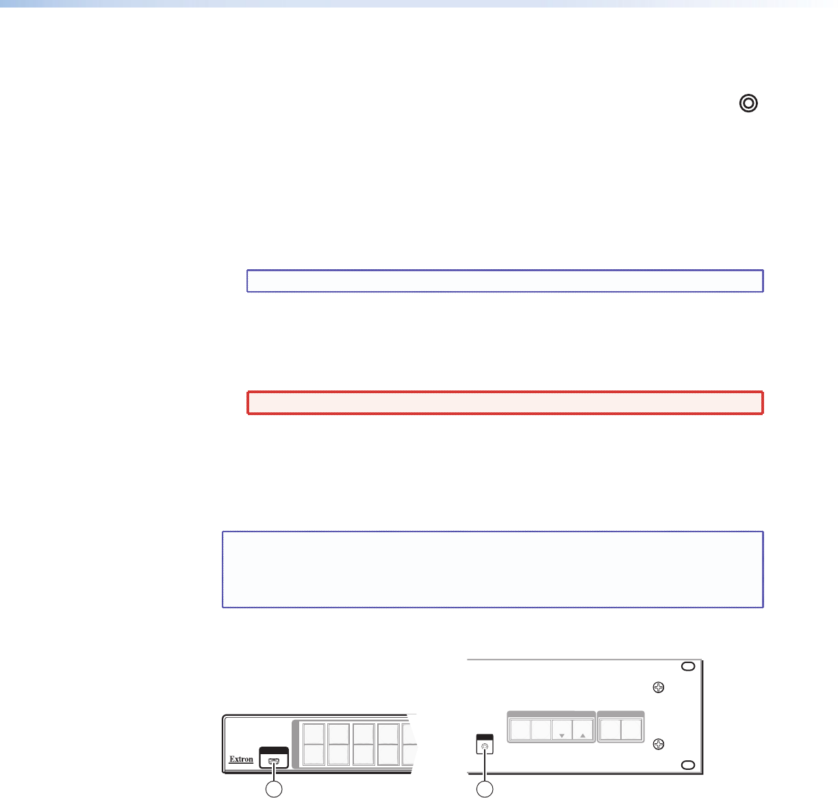
Figure 14 shows the Configuration port for the various MTPX Plus models.
AUDIO
VIDEO
I/O
CONTROL
ENTERPRESET
VIEW
ESC
MTPX PLUS SERIES SWITCHER
CONFIG
1
1
2
2
3
3
4
4
5
5
I
N
P
U
T
O
U
T
P
U
T
CONFIG
1514
MTPX Plus 128
All other MTPX Plus models
Figure 14. Front Panel Configuration Port
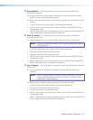
n Configuration port (MTPX Plus 128 only) — A mini USB B port.
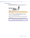
o Configuration port — A 2.5 mm mini stereo jack. The optional 9-pin D to 2.5 mm
mini jack TRS RS-232 cable, part number 70-335-01 (see figure 15, on the next page),
can be used for this connection.
MTPX Plus Series • Installation 20


