


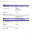
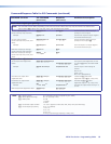
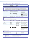

Command/Response Table for SIS Commands (continued)
Command Function
SIS Command
(Host to Unit)
Response
(Unit to Host)
Additional description
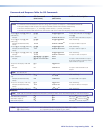
Local video output sync polarity
NOTE: The command structure differs, depending on the size of the matrix. Matrix sizes 816, 168, and 1616 do not need the local
output variable (
X1^
). Matrix sizes 128, 1632, 3216, and 3232 require the variable.
Set local output polarity
(matrix size 816, 168, and 1616)
EX1&
Opol
}
Opol
X1&]
Set the horizontal and vertical sync
polarity for a local output.
Example:
E
0Opol
}
Opol0
]
Set the local output to output negative
horizontal and vertical sync.
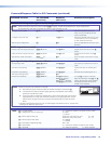
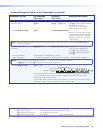
Set local output polarity
(matrix size 128, 1632, 3216, and
3232)
EX1^
*
X1&
Opol
}
Opol
X1^
*
X1&]
Set the horizontal and vertical sync
polarity for local output
X1^
.
Example:
E
2*0Opol
}
Opol2*0
]
Set local output 2 to output negative
horizontal and vertical sync.
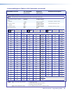
Read local output sync settings
(matrix size 816, 168, and 1616)
E
Opol
} X1&]
Read local output sync settings
(matrix size 128, 1632, 3216, and
3232)
EX1^
Opol
} X1&]
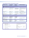
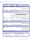
Output skew adjustment
Set all output skew adjustment
values
EX@
*
X1)
*
X1)
*
X1)
Oseq
}
Set a specific skew adjustment for the
TP output.
X1)
values are listed in RGB
order.
Oseq
X@
*
X1)
*
X1)
*
X1)]
Example:
E
2*0*0*4Oseq
}
Oseq02*0*0*4
]
Set the output 2 skew settings as
follows:
Red = 0 ns
Green = 0 ns
Blue = 8 ns (delayed 8 ns).
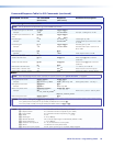
Increment one output skew
adjustment value
EX@
*
X1!
+Oseq
}
Oseq
X@
*
X1)
*
X1)
*
X1)]
Increase the
X1!
plane skew
adjustment output
X@
by 1 step (2 ns).
Decrement one output skew
adjustment value
EX@
*
X1!
-Oseq
}
Oseq
X@
*
X1)
*
X1)
*
X1)]
Decrease the
X1!
plane skew
adjustment output
X@
by 1 step (2 ns).
Example:
E
2*2-Oseq
}
Oseq02*0*0*3
]
Decrease the output 2 blue skew by 2 ns
to 6 ns.
Read output skew adjustment values
EX@
Oseq
} X1)
*
X1)
*
X1)]
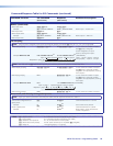
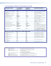
NOTE: X@ = Output number 01 – (maximum number of outputs for your model)
X1) = Skew adjustment range 00 – 31 (each step = 2ns)
X1! = Video plane 0 = red
1 = green
2 = blue
X1^ = Local video output number 1 or 2 (X1^ applies to matrix sizes 128, 1632, 3216, and 3232 only)
X1& = Local output sync polarity 0 = H- / V- (default)
1 = H+ / V-
2 = H- / V+
3 = H+ / V+
4 = No sync processing (composite, S-video, YUV)
MTPX Plus Series • Programming Guide 83