


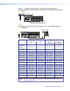
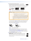
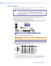
Figure 5 shows the recommended termination of TP cables in accordance with the
TIA/EIA T568A or TIA/EIA T568B wiring standards. You can use either standard with CAT
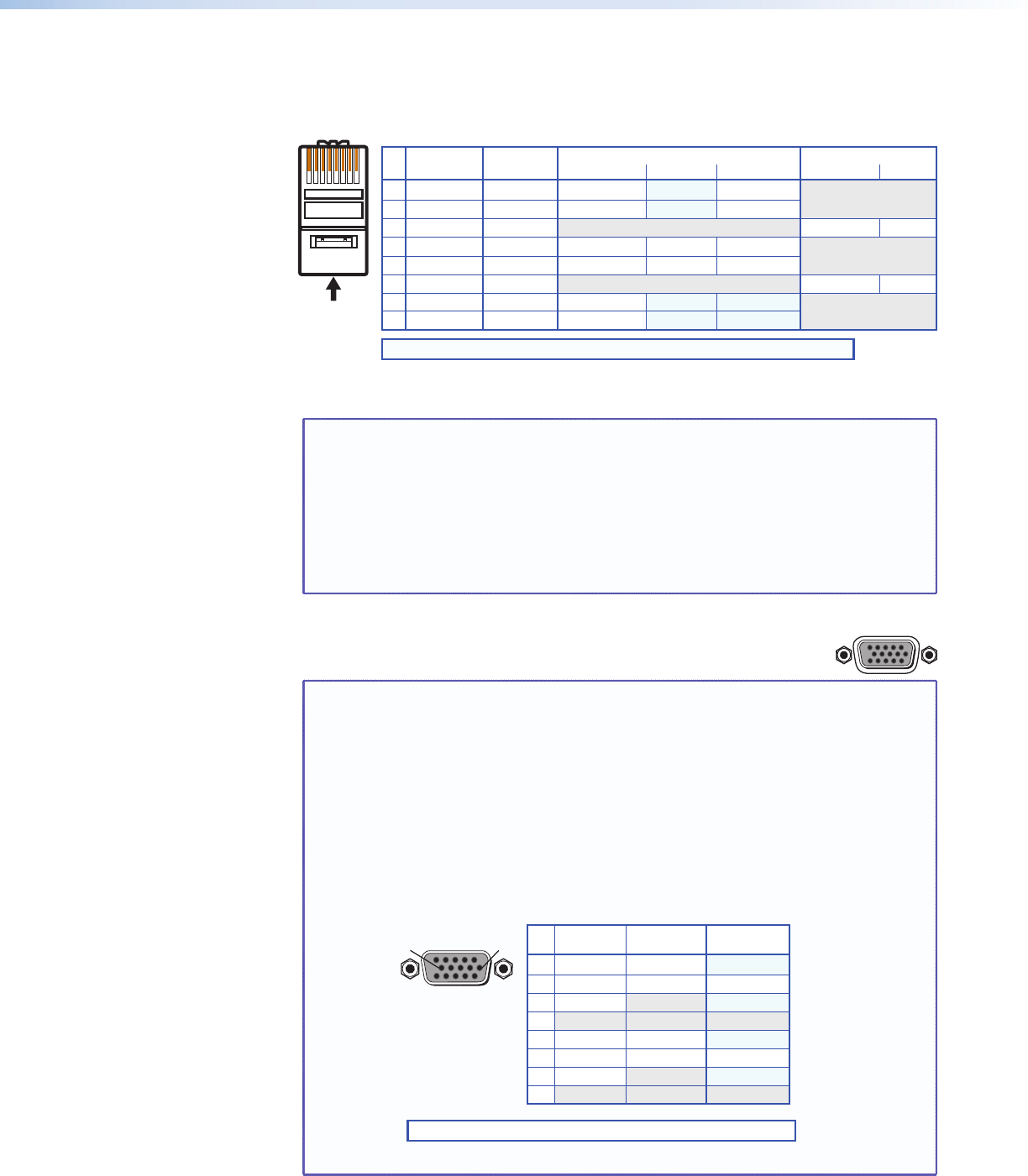
5, 5e, or 6 cable, but use the same standard on both ends of the cable.
5
Pin
1 Red+/V. sync+
2 Red–/V. sync–
3 RS-232+
Green-
6 RS-232-
Mono audio+
Mono audio-
7 Blue+/H. sync+
8 Blue-/H. sync-
4
Wire color
White-green
Green
White-orange
White-blue
Orange
White-brown
Brown
Wire color
T568A T568B Video input (via transmitter or local input) Secondary input
RGB
White-orange
Orange
White-green
White-blue
Green
White-brown
Brown
Green+Blue Blue
Reserved
Reserved
Video-
Reserved
Reserved
Reserved
Reserved
Composite
Chroma (C)+
Chroma (C)-
Luma (Y)+
Luma (Y)-
S-video
Video+
Stereo audio
RS-232
12345678
RJ-45
Connector
Insert Twisted
Pair Wires
Pins:
NOTE: If you are using Enhanced Skew-Free A/V cable, use the TIA/EIA T568A standard only.
Figure 5. TP Cable Termination
NOTE: Enhanced Skew-free A/V cable is not recommended for Ethernet/LAN
applications. This cable is specially designed for compatibility with the
Extron Twisted Pair products that are wired using the TIA/EIA 568A
standard.
The green, brown, and blue pairs of this cable have virtually identical
lengths and should be used to transmit the RGB signals.
The orange pair of this cable has a different length and should not be used
to transmit the RGB signals..
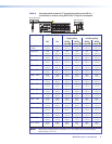
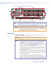
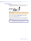
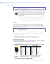
b Local Inputs (VGA) connectors — Connect analog computer-
RGB
video (RGB) sources to these 15-pin HD female connectors.
NOTES: • The video that is input on this connector, when it is tied to a TP output,
is converted to same type of the proprietary TP signal that is output by
the MTP 15HD transmitters. This allows you to eliminate some of the
transmitters in your system.
• When either the input or output of a tie is local (VGA), Extron
recommends that the MTP output or input be connected by a minimum
of 25 feet (7.5 m) of TP cable to prevent overpeaking.
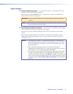
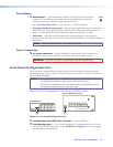
• The matrix switchers can also input and switch HD component video,
component video, S-video, or composite video by using the appropriate
adapters and the pins show in figure 6. No configuration of the switcher
is required for component or other non-RGB video formats.
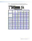
Pin
1
2 Video
3
6
7 Video return
Video 2*
Video 2 return*
Video 3*
Video 3 return*
8
4-5
Signal
R-Y
Y
B-Y
R-Y return
Y return
B-Y return
Signal
Component S-video Composite
Signal
Chroma (C)
Luma (Y)
Chroma return
Luma return
9-15
51
15 11
610
Female
* You can input and output additional, genlocked, composite video on these pins.
NOTE: Input only sync signals, no video signals, on the sync pins (13 and 14).
Figure 6. Other Video Formats on a VGA Connector
MTPX Plus Series • Installation 13