


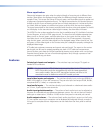
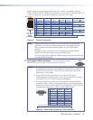
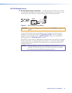
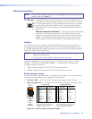
c Audio Inputs (local audio) connectors — Connect balanced or
unbalanced stereo audio inputs to these 3.5 mm, 5-pole captive screw
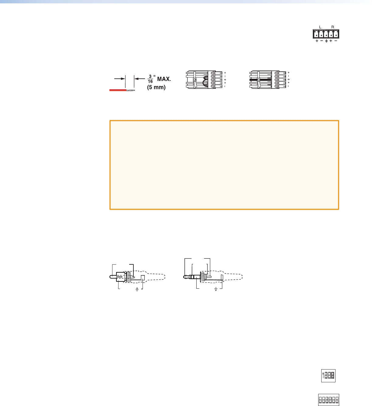
connectors. Connectors are included with each switcher, but you must
supply the audio cable. See figure 7 to wire a connector for the appropriate
input type and impedance level. Use the supplied tie-wrap to strap the audio cable to
the extended tail of the connector. High impedance is generally over 800 ohms.
LR
LR
Unbalanced Stereo Input
Balanced Stereo Input
(high impedance)
(high impedance)
Do not tin the wires!
Ring
Sleeve (s)
Tip
Sleeve
Tip
Sleeve
Tip
Tip
Ring
Figure 7. Captive Screw Connector Wiring for Audio Inputs
CAUTIONS: • The length of exposed wires is critical. The ideal length is 3/16 inch
(5 mm).
•
If the stripped section of wire is longer than 3/16 inch, the
exposed wires may touch, causing a short circuit.
• If the stripped section of wire is shorter than 3/16 inch, wires can
be easily pulled out even if tightly fastened by the captive screws.
• The captive screw audio connector can easily be inadvertently plugged
partially into one receptacle and partially into an adjacent receptacle.
This misconnection could damage the audio output circuits. Ensure
that the connector is plugged fully and only into the desired input or
output.
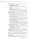
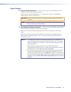
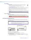
A mono audio connector consists of a tip and sleeve. A stereo audio connector consists
of a tip, ring and sleeve. See figure 8 to identify the tip, ring, and sleeve parts of the
connector when you are making connections for the switcher from existing audio
cables. The ring, tip, and sleeve wires are also shown on the captive screw audio
connector diagrams, figure 7 and figure 10.
Tip (+)
Sleeve ( )
Sleeve ( )
Ring (
-
)
Tip (+)
RCA Connector
3.5 mm Stereo Plug Connector
(balanced)
Figure 8. Typical Audio Connectors
The audio level for each input can be individually set via the front panel or remote
control to ensure that the level on the output does not vary from input to input (see
“Viewing and Adjusting the Input Audio Level“ in the “Operation” section).
You can also use SIS commands (see the “Programming Guide” section), the Matrix
Switchers Control Program (see the “Matrix Software“ section), or the HTML pages
(see the “HTML Operation” section).
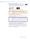
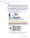
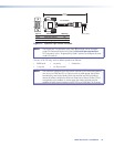
d Input Select switches (switchers other than the
INPUT SELECT
ON
LOCAL
RJ - 45
123
LOCAL
RJ-45
MTPX Plus 128) — For inputs 1 through 3 (matrix sizes 1616 and smaller,
excluding the MTPX Plus 128) or inputs 1 through 6 (matrix sizes 1632 and
larger), set these DIP switches to the Local (up) position to select the local
(RGB video and audio) input. Set the DIP switches to the RJ-45 (down) position
to select the MTP input.
MTPX Plus Series • Installation 14