


IN1606 and IN1608 Series Scaling Presentation Switcher • Installation 13
Installation Overview
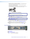
1. Turn off or disconnect all related equipment. Ensure that video sources and output
displays are all turned off and disconnected from the power source.
2. Mount the scaler (see Mounting on page 123).
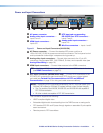
3. Connect input sources (see Power and Input Connections on page 14).
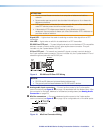
4. Connect output devices (see Output Connections on page 16).
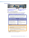
5. Connect desired control devices (see Control Connections on page 17 or
IPCP Pro 350 Control Processor Connections on page 18).
6. Connect a power source to the scaler (see Power and Input Connection on
page 14).
7. Configure the scaler (see Control Methods on page 10).
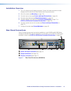
Rear Panel Connections
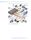
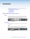
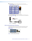
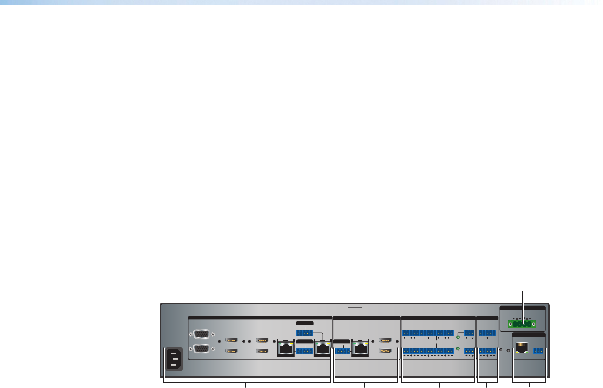
Figure 7 shows the rear panel connectors available on most IN1606 and IN1608 Series
models (the IN1608 SA is used an example). For information on the IPCP Pro 350 control
processor module, see IPCP Pro 350 Control Processor Connections on page 18.
100-240V ~ -- A MAX
1
2
CONFIGURABLE
HDMI
HDMI
5
6
7
8
C
RS-232 IR
RS-232 IR
TxRx TxRxG
TxRx Tx RxG
TxRx Tx RxG
HDMI
A
B
3
4
INPUTS
OUTPUTS
TxRx
RS-232
G
LAN
2x25W(8Ω)/2x50W(4Ω)
RESET
AUDIO INPUTS
OUTPUTS
REMOTE
LL1R R
L2
R
L
3
R
CLASS 2 WIRING
L4
R
L5R
+48V
+48V
12
LR
VARIABLE
IN1608 SA
2
MIC/LINE
L6
R
SIG LINK
DTP IN
SIG LINK
DTP IN
SIG LINK
DTP OUT
50/60 Hz
RS-232 IR
OVER DTP
OVER DTP
OVER DTP
AMPLIFIED OUTPUT
AABBC
B
A
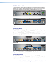
Power and input connectors (see page 14)
B
Output connectors (see page 16)
C
Control connectors (see page 17)
Figure 7. Rear Panel Connectors (IN1608 SA)