


IN1606 and IN1608 Series Scaling Presentation Switcher • Installation 20
Analog Audio Connection
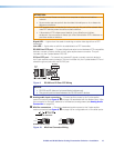
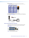
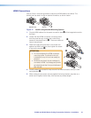
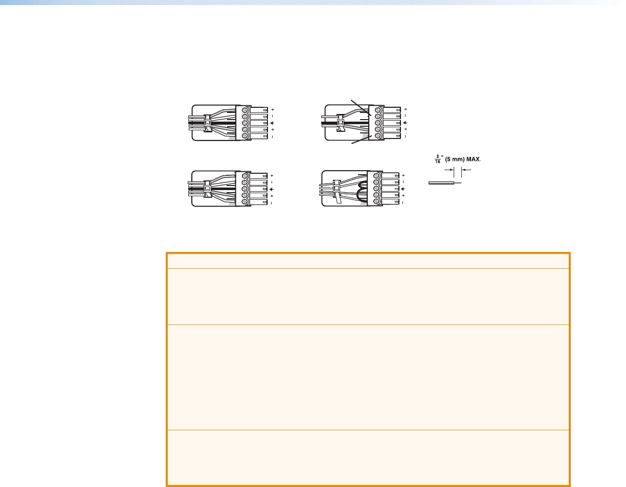
Wire the audio input and output connectors as shown in figure 16. Use the supplied tie
wrap to strap the audio cable to the extended tail of the connector. This does not apply to
the amplified audio output connector on the SA and MA models.
Balanced Audio Output
Tip
Ring
Tip
Ring
Slee
ves
Unbalanced Audio Output
Tip
No Ground Here
No Ground Here
Tip
Sleeves
LR
LR
Unbalanced Audio InputBalanced Audio Input
Tip
Ring
Tip
Ring
Slee
ves
Tip
Sleeve
Sleeve
Tip
LR
LR
Do not tin the wires!
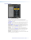
Figure 16. Analog Audio Wiring Configuration
ATTENTION:
• For unbalanced audio, connect the sleeves to the ground contact. Do not connect
them to negative (–) contacts.
• Pour l’audio asymétrique, connectez les manchons au contact au sol. Ne PAS
connecter les manchons aux contacts négatifs (–).
• The length of the exposed wires in the stripping process is critical. The ideal length
is 3/16 inch (5 mm). If the exposed portion is longer, the wires may touch, causing
a short circuit between them. If the exposed wires are shorter, they can be easily
pulled out, even if tightly fastened by the captive screws.
• La longueur des câbles exposés est primordiale lorsque l’on entreprend de les
dénuder. S’ils sont un peu plus longs, les câbles exposés pourraient se toucher et
provoquer un court circuit. S’ils sont un peu plus courts, ils pourraient sortir, même
s’ils sont attachés par les vis captives.
• Do not tin the wires. Tinned wire does not hold its shape and can become loose
over time.
• Ne pas étamer les câbles. Les câbles étamés ne sont pas aussi bien fixés dans les
terminaisons des connecteurs à vis captives et pourraient sortir.