


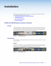
IN1606 and IN1608 Series Scaling Presentation Switcher • Installation 15
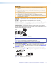
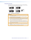
ATTENTION:
• Do not connect these connectors to a computer or telecommunications
network.
• Ne connectez pas ces ports à des données informatiques ou à un réseau de
télécommunications.
• DTP remote power is intended for indoor use only. No part of the network that
uses DTP remote power should be routed outdoors.
• L’alimentation DTP à distance est destiné à une utilisation en intérieur
seulement. Aucune partie du réseau qui utilise l’alimentation DTP à distance ne
peut être routée en extérieur.
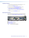
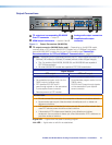
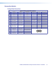
Signal LED — Lights when the scaler is receiving an active video signal from a DTP
transmitter.
Link LED — Lights when a valid link is established to a DTP transmitter.
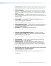
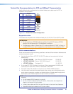
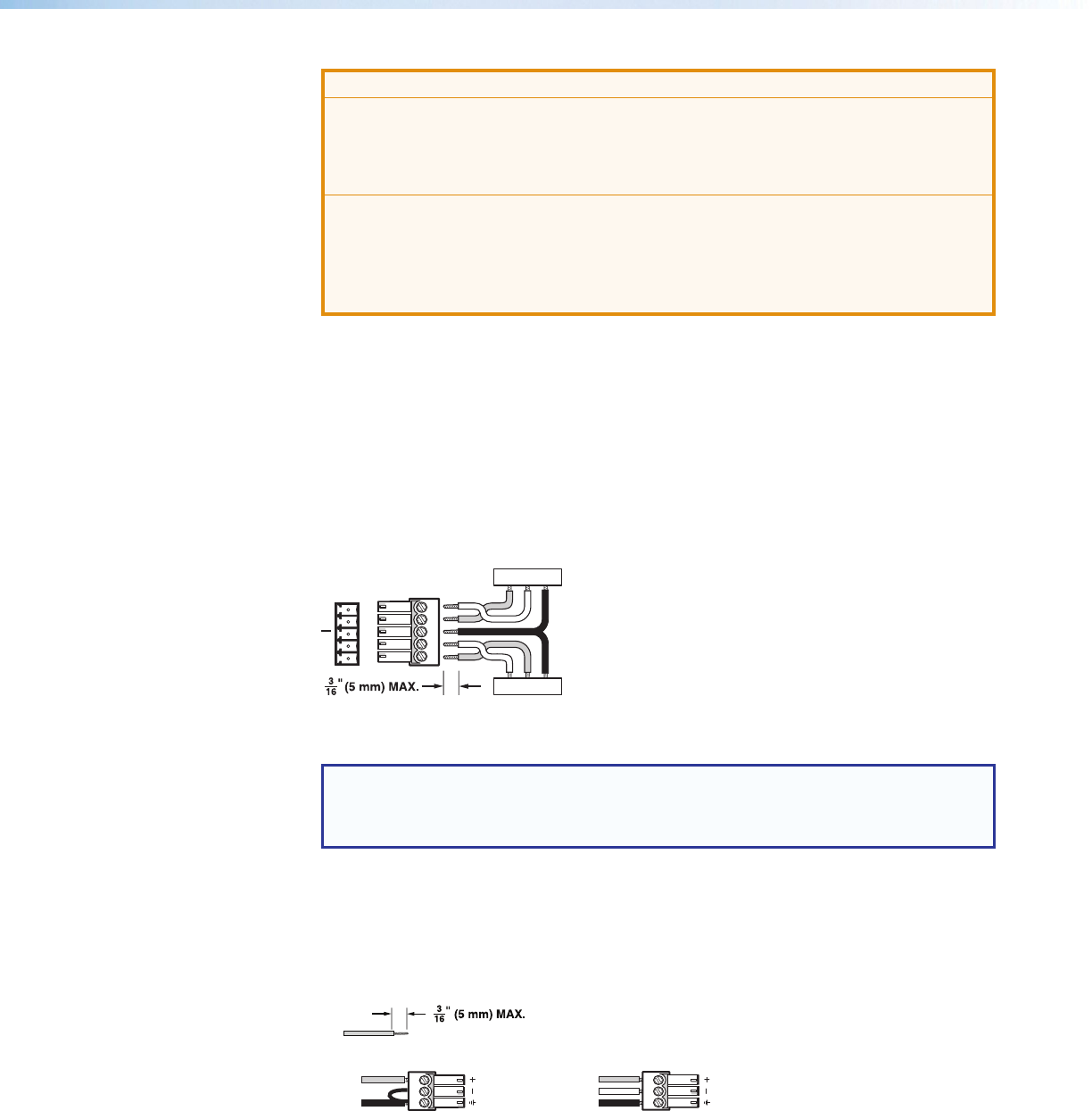
RS-232 Over DTP port — To pass bidirectional serial control between DTP-compatible
devices, connect a control device to the 5-pole captive screw connector. This port
includes only the 3 poles labeled “RS-232.”
IR Over DTP port — To transmit and receive IR signals, connect a control device to
the 5-pole captive screw connector. This port includes only the 2 poles labeled “IR” and
shares the ground pole with the RS-232 port.
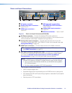
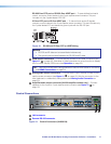
Tx/Rx
Pins
RxTx
RS-232
RxTx
TxRx
RxTx
IR Device
RS-232 De
vice
G
G
G
IR
Figure 9. RS-232 and IR Over DTP Wiring
NOTES:
• RS-232 and IR data can be transmitted simultaneously.
• The ground pole is shared between the RS-232 and IR devices.
E
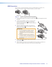
Analog audio input connectors — Connect audio sources to the 5-pole captive
screw connectors (see figure 8,
E
on page 14) associated with the desired input. Wire
the connector for line level, balanced or unbalanced, analog stereo (see Analog Audio
Connection on page 20).
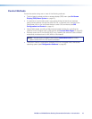
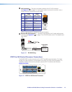
F
Mic/line connectors — Connect unbalanced audio sources to the 3-pole captive
screw connectors (see figure 8,
F
on page 14) for configurable mic or line level inputs.
Balanced Mic InputUnbalanced Mic Input
Tip
Ring
Tip
Sleeve Sleeve
Do not tin the wires!
Figure 10. Mic/Line Connector Wiring