


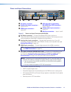
IN1606 and IN1608 Series Scaling Presentation Switcher • Installation 18
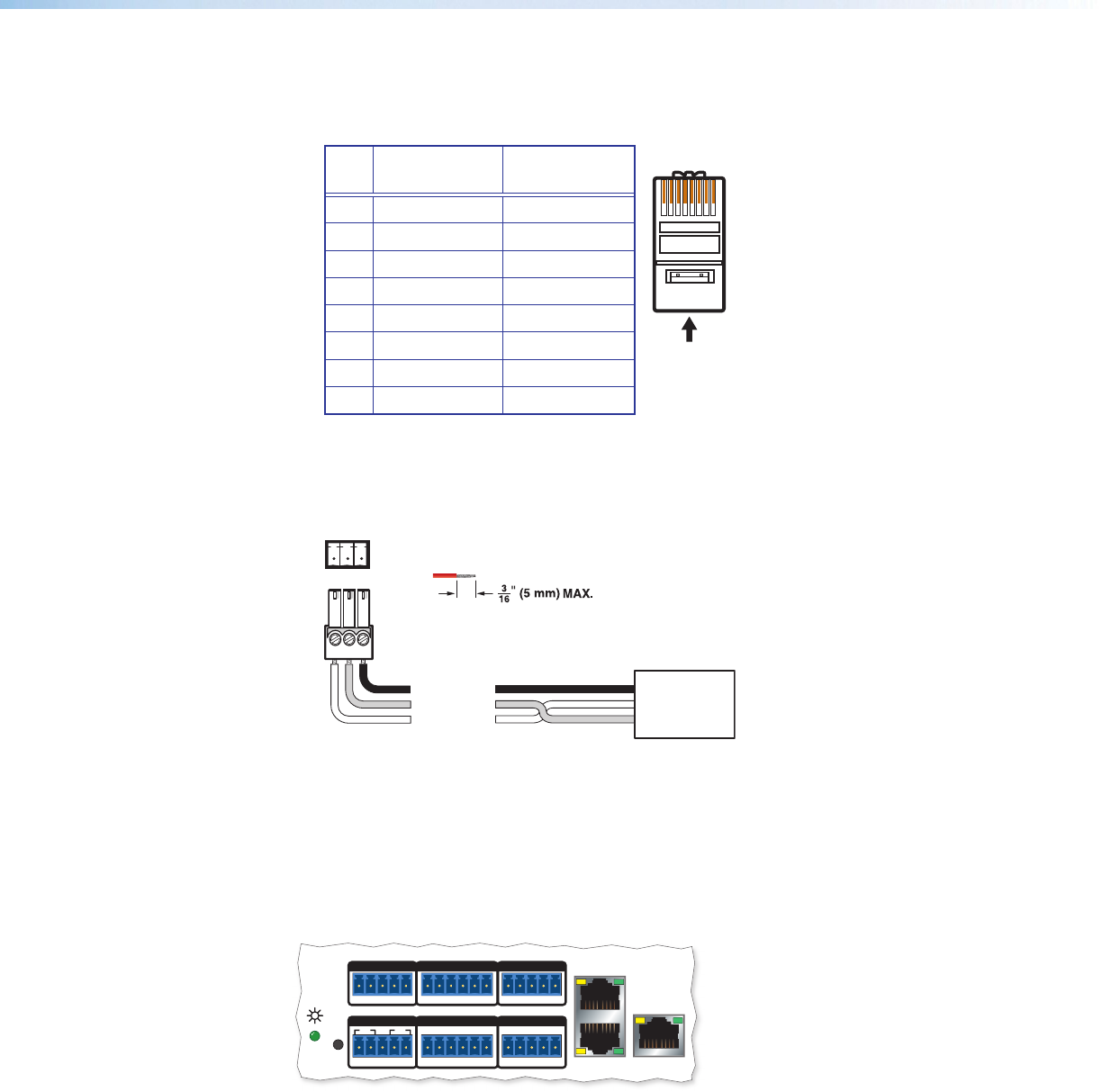
A
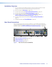
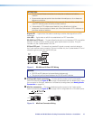
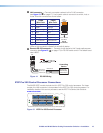
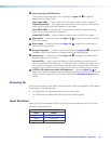
LAN connector — Connect a computer network to this RJ-45 connector
(see figure 13,
A
on page 17). Use a patch cable to connect to a switch, hub, or
router. Wire the connector as shown below.
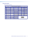
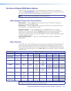
Pin T568A
Wire Color
T568B
Wire Color
1 White-green White-orange
2 Green Orange
3 White-orange White-green
4 Blue Blue
5 White-blue White-blue
6 Orange Green
7 White-brown White-brown
8 Brown Brown
LEDs on this connector indicate link and activity status.
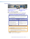
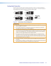
B
Remote RS-232 connector — Connect a host device to this 3-pole captive screw
connector (see figure 13,
B
on page 17) for RS-232 serial control. The default baud
rate is 9600.
Do not tin the wires!
Controlling
Device
Ground (G)
Receive (Rx)
Transmit (Tx)
Ground (G)
Receive (Rx)
Transmit (Tx)
Bidirectional
Tx Rx G
RS-232
Figure 14. RS-232 Wiring
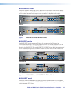
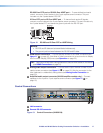
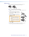
IPCP Pro 350 Control Processor Connections
The IN1608 IPCP models include a built-in IPCP Pro 350 control processor. For these
models, the LAN connector is incorporated in the IPCP Pro 350 control processor. For
installation details of this control processor, see the IPCP Pro Series User Guide at
www.extron.com.
R
23
GTx Rx GTx Rx
COM 2COM 3
RELAYS
2143CC
COM 1
GTx Rx
RTSCTS
IR/SERIAL
1
SG
2
SG
1 234G
DIGITAL I/O
eBUS
+V +S -S G
PWR OUT = 6W
1
Figure 15. IPCP Pro 350 Control Processor
12345678
RJ-45
Connector
Inser
t T
wisted
Pair Wires
Pins: