


Chapter 7 109
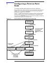
Configuring a Point-to-Point Node
Configure a Point-to-Point Network Interface
Configure a Point-to-Point Network Interface
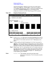
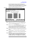
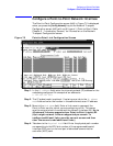
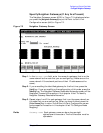
The Point-to-Point Configuration screen (#44) in Figure 7-2 is displayed
when you press the
[Config Network] key at the Network Transport
Configuration screen (#42) with an NI type of 2 (Point-to-Point). Refer
Chapter 5 , “Introductory Screens,” for information on the Network
Transport Configuration screen.
Figure 7-2 Point-to-Point Link Configuration Screen
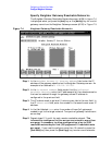
Step 1. In the IP address field, enter the internet protocol (IP) address for the
node being configured. An example of an address is:
C 192.191.191 009.
Step 2. The IP subnet mask is optional. If entering one, tab to the IP subnet
mask field and enter the number in the same format as an IP address.
Step 3. Move to the Link Name field. Enter a link name to represent the
Point-to-Point card for which you are configuring a link. This name
must be unique to both the node and the network interface (NI). Up to
40 network links are supported per Point-to-Point (router) NI.
(Up to eight network links are supported per screen. To
configure additional links, save the current screen and then
clear the screen to add additional links.)
Step 4. Tab down to the Physical Path field. Enter the physical path number
corresponding to the SPU slot number of the programmable serial
interface (PSI) card, or slot and part of advanced communication
controller (ACC) card.