


50 Chapter3
Planning Your Network
Network Worksheets
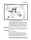
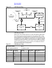
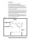
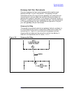
Figure 3-2 LAN Network Map
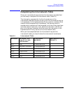
LAN Network Table
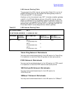
Refer to the LAN network map to fill in the LAN network table (Table
3-2). The first column lists the names of all the nodes on NET1. Each
node is assigned an IP address that is unique within the network. Only
the node portion of the IP address is listed since the IP network address
is noted at the top of the table. In the third column of Table 3-2, node B
is shown as a proxy server. The fourth column lists node B as a gateway
node. In the Implementation Priority column, the nodes are ranked in
the recommended order of configuration.
DTC
DTC
A
N1
N2
N3
NET1
C 192.001.001.XXX
LAN
B
GATEWAY NODE
TO NET2:
NET4
C 192.004.002.XXX
TOKEN RING
GATEWAY NODE
TO NET4:
NET3
C 192.003.251.XXX
X.25
NET2
C 192.002.250.XXX
POINT-TO-POINT
NET5
C 192.005.252.XXX
LAN
H
G
GATEWAY HALF
GATEWAY HALF
ROUTER
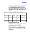
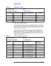
Table 3-2 LAN Network Table
NETWORK NAME: NET1
IP NETWORK ADDRESS C 192.001.001 XXX
NODE NAME IP NODE
ADDRESS
PROXY
SERVER (Y/N)
GATEWAY
NODE (Y/N)
IMPLEMENTATION
PRIORITY
A 001 2
L1 002 3
L2 003 4
L3 004 5
B 005 YES YES 1