


92 Chapter6
Configuring a LAN Node
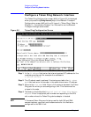
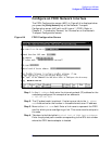
Configure a LAN Network Interface
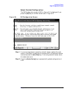
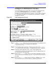
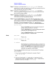
Step 6. Tab down to the field called Physical path of LANIC. Enter the
physical path number corresponding to the SPU slot number where the
LAN interface controller card is located.
Step 7. Tab down to the field called Enable Ethernet (Y/N). By default,
ethernet is enabled. Change the field to N if you do not want ethernet
and the ARP protocol enabled.
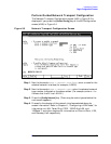
Step 8. Tab down to field called Enable IEEE 802.3 (Y/N). By default,
IEEE 802.3 is enabled. Change the field to N if you do not want
IEEE 802.3 and the Probe protocol enabled.
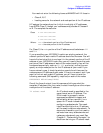
Step 9. Press the
[Save Data] key to save the LAN link configuration. If you
need to identify neighbor gateways, press the
[Neighbor Gateways] key
and proceed to the section in this chapter called “To Identify Neighbor
Gateways.” Otherwise, proceed to Chapter 10 , “Validating and
Cross-Validating with SYSGEN,” and press the
[Validate Netxport] key.
Optional Keys
Press the
[List NIs] key to list the names and types of
already configured network interfaces.
Press the [Delete NI] key to remove a configured network
interface from the configuration file.
Press the [Read Other NI] key to call up a previously
configured Network Interface name.
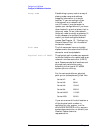
Fields Node name
Display only.
Network Interface (NI) name
Display only.
IP address
The IP address is an address of a node on a network. An
IP address has two parts: a network portion and a node
portion. The network portion must be the same for all
nodes on a LAN network; the node portion must be
unique for all nodes on a LAN network.
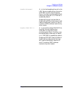
There are two methods of entering an internet protocol (IP) address
within NMMGR:
1. Enter the fully qualified IP address (for example, Class C,
C 192.191.191 009).
OR
2. Enter only the network (
nnn
) and node (
xxx
) portions of the IP
address as four positive integers between 0 and 255 separated by
periods or blanks (for example, 15.123.44.98).